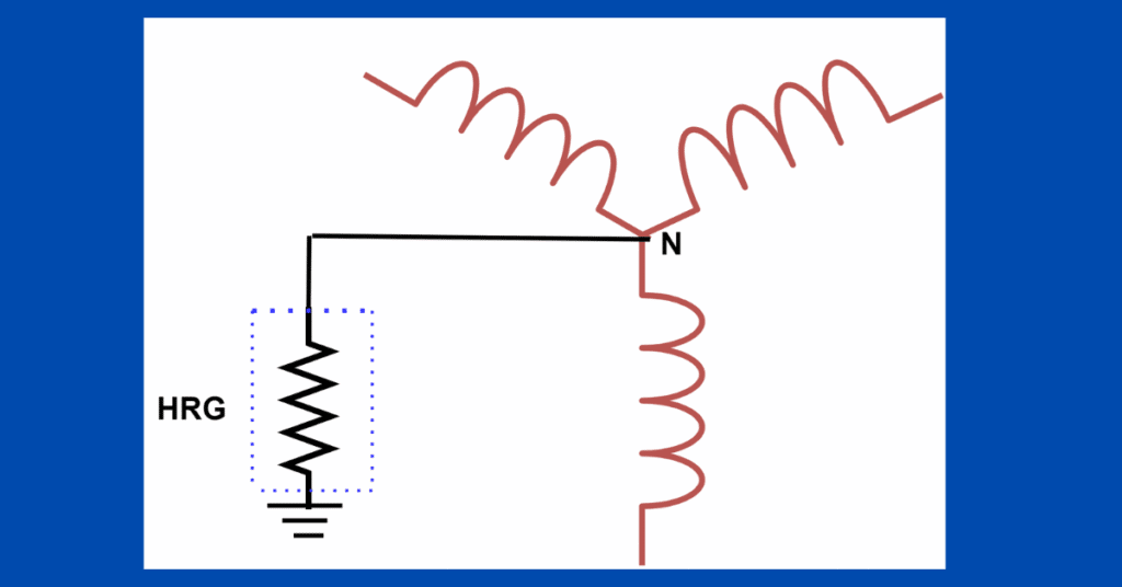
In a High Resistance Grounding (HRG), the neutral point or star point of the transformer or generator is connected to one end of high resistance and another end of the resistance is connected to the ground. High resistance grounding is used in applications where total interruption of the supply can not be afforded.
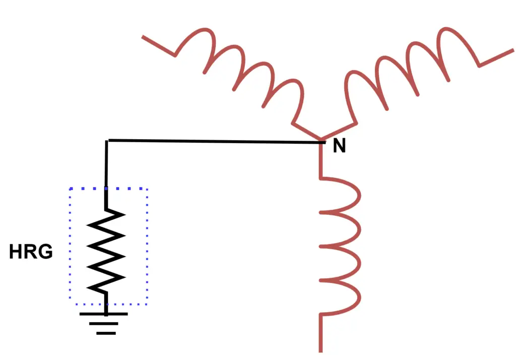
In a solid grounding system, the neutral point is directly connected to the earth, and thus very high fault current flow through the equipment to the ground. Contrary to this, in the HRG system, the fault current is limited to 10 Ampere or less by the neutral grounding resistor. it is limiting fault current does not cause escalating point of fault damage. Moreover, it limits the touch potential. The fault current flowing through the neutral can easily be detected with the protection system to locate ground faults.
In a solid grounding, the phase voltage of the sound phases does not rise because the neutral point is clamped to the earth’s potential. However, in the case of HRG, the phase voltages of the healthy phases will increase during the ground fault. The increasing of phase voltage during ground fault may cause an increased possibility of a second ground fault.
To avoid this, line-to-ground and line-to-line insulation need to be improved to take care of increased phase voltages during fault. High resistance grounded system reduces the possibility of arc flash between line-to-ground to make the system safer, however, it does not limit line-to-line arc flash energy. one of the advantages of the HRG system is that it controls the transient overvoltage phenomenon which happens in the case of the ungrounded system.
In an HRG system, the fault current is limited by high resistance in the neutral and earth circuit. Thus, the fault current gets limited and the protection can not be ensured with fuses or circuit breakers as protective devices. The fault current is sensed by the current transformer by measuring the current in the neutral circuit.
The output of the relay can be used to trip the circuit breaker or as an alarm. The system may be kept operating even after an earth fault occurs in the system. Thus, uninterrupted supply can be ensured. The detected ground fault can be repaired later on in a planned manner
High resistance grounding and protective relays
In a solid grounding system, the system impedance only limits the fault current. The system impedance is generally low and the high magnitude of earth fault current is similar to short circuit current flow through the neutral circuit and, it causes overcurrent protective devices to trip the faulty section.
In an HRG system, a current sensing protective relay is used to detect the earth fault. The relay can be used for either tripping the system or for alarm only. In an HRG system, overcurrent devices like circuit breakers and fuses can not isolate the faulty circuit as the current flowing through the equipment gets limited by high resistance connected in the grounding circuit.
Typical applications for HRG
The HRG is adopted where high availability of the power supply is desired and power outage is not desired due to a safety viewpoint. The electrical system of the mining industry operates in harsh environments like dust, moisture, and vibration. The insulation of electrical systems is more vulnerable in the mining industry and on the other hand uninterrupted supply is a must from a safety point of view. The HRG system is a good choice for the mining industry.
One installation can rely on HRG to allow continued operation with one ground fault. The other electrical installation may be provided with a ground fault relay with selective tripping coordination.
In case of a fault, the upstream feeder must trip first to isolate the supply system and the main supply system having HRG must not trip, it should output an alarm only.