The starter is very important and necessary for starting the electric motor. There are two types of motors that are widely used: DC motors and AC motors. A motor is an electrical machine used for various applications in industry, traction, or any other sensitive operation. An ideal motor is one that has a low starting current and a high starting torque. But inherently, motors, whether AC or DC, are not like that.
Why Starter for Electric Motor?
Because of the motor’s inherent nature, if a motor directly receives full supply voltage, It will draw a massive amount of electric current from the source during start, leading to overheating of the motor windings and a considerable amount of voltage drop at the source. To avoid this from happening, we need to install starters. Let’s understand this by an example:-
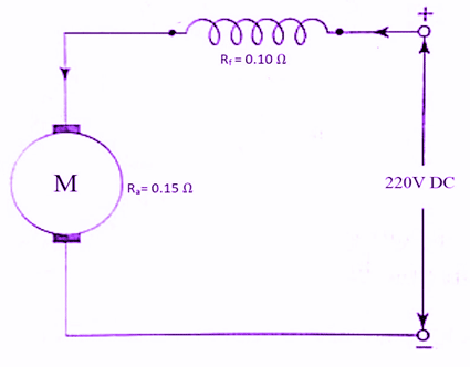
Let’s say we have a DC series motor (as shown in the diagram) connected to a 220V source with an armature resistance, Rₐ= 0.15 Ω, and field coil resistance, Rf = 0.10 Ω.
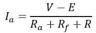
The operating equation of a DC motor is given as
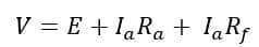
Where V is the source voltage, and E is the back-emf generated by the motor. Back-emf is the emf generated by the motor when it begins to rotate, and it opposes the source voltage as well as the armature current as per Lenz’s law of Electromagnetic induction. The back EMF depends on the armature velocity in revolution per minute(rpm) given by N.

Now, during the start of the motor, the armature velocity is zero, N=0. Therefore, the back EMF at the starting point of the motor is also zero, i.e., E=0. So, the operating equation becomes
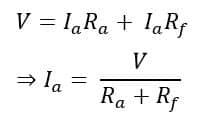
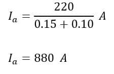
Now, given that
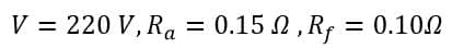
Therefore,
As we discussed earlier, the motor’s starting current is objectionably very high. This may lead to winding burn-out and permanent damage to the motor. Here comes the role of a starter.
An electric motor starter has a set of series-connected resistors that are added before starting the motor and are cut out gradually as the motor picks up speed. It is equivalent to a Rheostat.
The picture above shows a DC motor starter. As you can see, a set of series connected resistors is cut down in phases as the motor picks up by moving the handle through tapping points 1-2-3-4-5-6, as shown.
During the start, the handle remains at position 1 (OFF), and hence, the entire set of resistors is connected in series with the armature resistor. Let’s consider the total added resistance is R. So, the equation of the armature current becomes:
It’s evident that the denominator part of the equation increases due to the addition of R, and hence, the armature current during the motor start goes down. Thus, the motor is protected from burnout during the start.
Once the motor picks up speed, the back-emf also begins to rise as back-emf is dependent on the rpm of the motor. As the back emf begins to develop, the added resistance is cut down gradually by moving the handle through the different tapping points. The added resistance is cut down at the rated speed, and the back EMF controls the armature current effectively.
But why do we need to cut the added resistance?
Let’s consider the rated speed of the motor is Nr for which the back-emf of the motor is E. Then the voltage equation of the motor with added resistance R becomes
Therefore,
Thus, with the motor picking up the required speed, the back-emf E increases, and the numerator value of the equation of Ia goes down, thus effectively decreasing the armature current. We don’t need an added resistor to control the armature current in this scenario. If kept added, it will lead to unwanted power loss, i.e., I2a *R loss. That’s why it is cut down gradually as the motor picks up speed.
Types of Starter for DC Motor
There are three types of DC motor starters. They are-
Two-point Starter
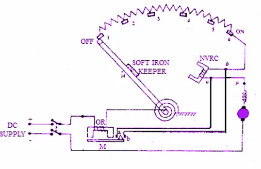
Protection against starting current is just a part of what this starter can do. The picture shown below is of a 2-point starter for a DC series motor.
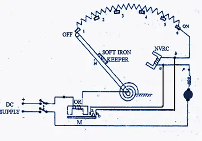
A DC series motor has armature(A) and field(F) connected in series; hence, we get two connection points in such types of starters. The handle H remains in the OFF position before starting the motor, or it is confirmed before starting the motor. Gradually, the handle is moved from the OFF point (tap 1) to tap 2 as the motor starts rotating. Similarly, it is moved through taps 3, 4, 5, and finally, tap 6, while it keeps on adding speed and reducing the added starting resistance. At point 6, the motor attains the rated speed, and there is enough back-emf generated to control the armature current.
At tap point 6, the added resistance is completely zero, and the motor achieves the rated current, which also energizes the No-Volt Release Coil (NVRC), also known as the Holding Coil (HC). Being energized satisfactorily, it holds the handle due to its electromagnetism at its place and avoids the handle spring to attract the handle back to the OFF position. That’s why it is called Holding Coil.
At the same time, if the motor is lightly loaded or unloaded or there is no power supply, the required armature current is low or zero, and thus, the Holding Coil isn’t energized enough to keep the handle at point 6. Thus, it allows the spring action of the handle to attract it back to the OFF position, and hence, the motor is protected from attaining dangerously high speed at no load, as happens in the case of a DC series motor.
Another coil shown in the picture is called the OR coil or Overload Release coil. If the motor is overloaded or if there is a fault causing the motor to draw a huge amount of current, the OR coil energizes satisfactorily and attracts the soft iron ‘M.’ This causes points ‘ a and ‘b’ of the NVRC to short-circuit and immediately release the handle. The spring takes over and brings the handle back to the OFF position.
Three-point Starter
A 3-point starter for an electric motor is similar in operation to that of a two-point starter. This starter is used in the case of a DC Shunt motor where the field and the armature connections are parallel to the source voltage. Thus, we get three connection points, Line (L), Armature (A), and Field (F), hence the name. The starting added resistance is directly connected to the armature winding while the Holding Coil (HC) or the No-Volt Release coil(NVRC) is connected in series with the field. Finally, both the armature and field connections are connected in parallel to the source voltage.
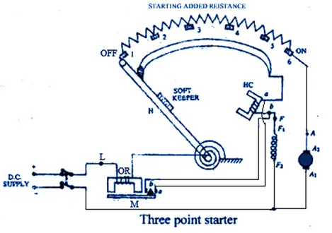
As the circuit shows, the field winding is connected to the source voltage during start, and it receives the normal field current, causing the generation of field flux as required. The handle is moved gradually through the tap points, thus causing the motor to rotate and the added resistance to go down. The NVR coil receives current equal to that of the field coil and energizes enough to hold the handle(H) once it reaches tap point 6, where the motor runs at rated speed, and the huge armature current is kept in check by the motor’s back emf.
Just like in the case of the 2-point starter, the overload Release (OR) coil attracts the soft iron bar M during overload, which causes the holding coil to short circuit, and thus, the handle returns to the OFF position due to spring action.
Four-point starter
A four-point starter is similar in operation to a 3-point starter except that the Holding Coil or the No-Volt Release Coil is connected separately through a limiting resistance R‘ instead of in series with the field coil. Thus, both the field coil and the Holding Coil are separate.
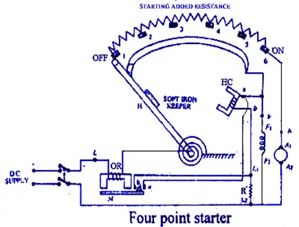
When the Overload Release (OR) coil operates during overload, the holding coil terminals are short-circuited, and the current passing through the same is controlled by the limiting resistance R‘ instead of passing through the field coil. The limiting resistance avoids short-circuiting of the supply as well as short-circuit current passing through the field coil. The rest of the operation of this starter is similar to its three-point counterpart.
In this way, starters protect costly electric motors as well as motor-based applications against situations like high starting current, overloading, or no-load/light-loaded conditions.
Starter of AC motors
AC motors, like induction motors, behave like secondary shorted transformers during the start, which causes a huge amount of current to be withdrawn. Thus, there are various starters like DOL starter, Star-Delta starter, Rotor-resistance starter, stator-resistance starter, soft starter, Auto-transformer starter, etc., for AC electric motor, which operate on the same principle of either lowering the supplied voltage at the start or connecting additional resistance to lower the objectionably high starting current.