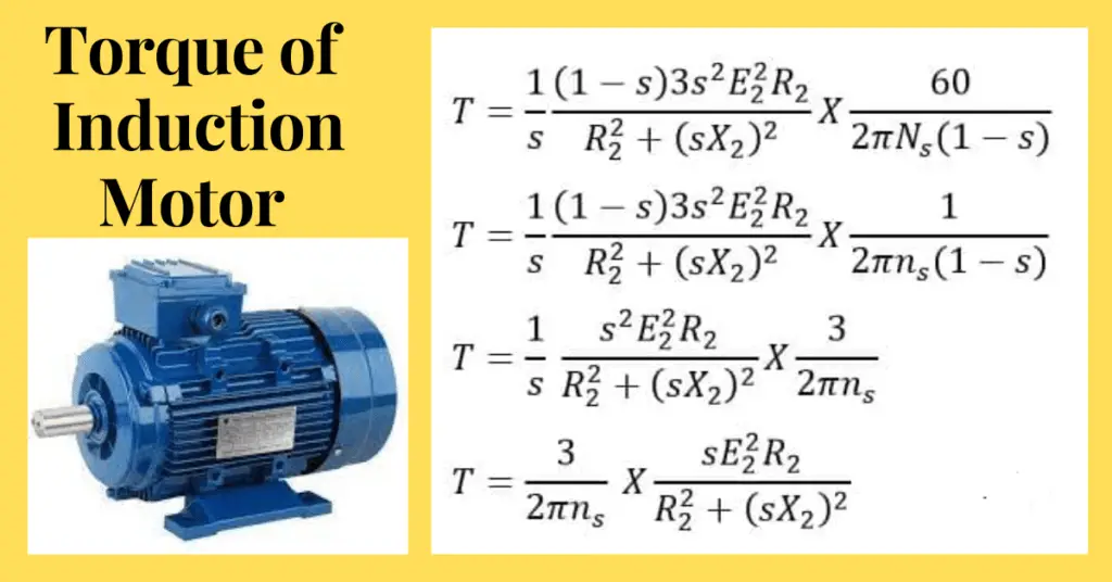
In this article, we will derive the torque equation of three phase induction motor. The torque is the turning ability of an induction motor.
When the stator of the three-phase induction motor receives a three-phase power supply, it produces a rotating magnetic field in the air gap of the induction motor. The air gap of the motor is the space or clearance between the stator and the rotor. The flux produced by the stator travels through the air gap and it links to the rotor conductor. The linking flux to the rotor produces a voltage in the rotor winding.
Do this voltage alone can rotate the motor? No
The rotating torque produces only when the current flows in the rotor. If you recall the construction of a squirrel cage induction motor, its rotor winding is star-connected and short-circuited at the end rings. In the case of slip ring induction motor the rotor circuit is connected to an external resistance for obtaining high starting torque, In both types of induction motors, thus, the rotor circuit forms a closed circuit. The voltage produced in the rotor is the driving force for the rotor current and the short-circuited rotor provides a closed path to the electric current. This way, current flows in the rotor current.
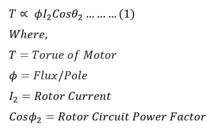
The rotor current flowing in the rotor winding interacts with the air gap flux. As a result, the torque is produced because of the interaction between the flux and the rotor current. The rotor current depends on the voltage produced in the rotor and the power factor of the rotor circuit. Thus, we can say that the torque produced in the rotor depends on flux, rotor current, and its power factor.
We can express the torque relationship with flux, rotor current, and its power factor by following mathematical expressions.
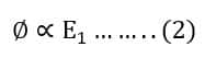
The flux produced in the air gap depends on the stator EMF (E1). The stator EMF is solely responsible for the production of magnetic flux. Thus, we can say the flux is proportional to the stator EMF.
The voltage transformation ratio(K) of the induction motor is the ratio of rotor voltage to stator voltage. We can express the relationship between the voltage transformation ratio(K), stator EMF, and rotor EMF by the following mathematical relationship.
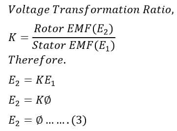
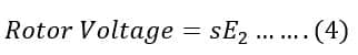
The rotor-induced voltage(E) depends on the speed at which the motor runs. The slip of the motor shows the difference between the synchronous speed(Ns) and the actual rotor speed(N). The voltage induced in the rotor(E2) depends on the difference between the synchronous speed and the actual speed or slip(s) of the motor.
Therefore, the rotor voltage under motor running conditions is;
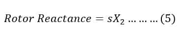
The rotor current(I2) of the motor depends on the rotor voltage and impedance of the rotor. The rotor winding has resistance and reactance. The resistance of the rotor is fixed for a particular motor, however, the rotor reactance is frequency dependent. The rotor frequency reduces with speed increase, in other words, we can say the rotor reactance is slip-dependent.
Thus, the rotor reactance in motor running conditions is;
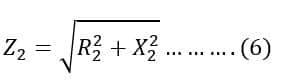
Now, we can calculate the rotor impedance(Z2),
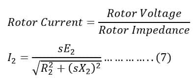
The rotor current (I2)can be calculated by applying ohm’s law,
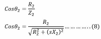
The power factor of the rotor circuit is the ratio of rotor resistance to rotor impedance. The power factor of the rotor circuit is;
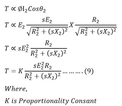
Putting the value rotor current I2, flux and power factor cosθ2 in the torque equation(1), we get,
Now, we will calculate the value of the proportionality constant(K).
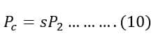
Let the rotor input power, rotor copper loss, and rotor mechanical power output is P2, Pc, and Pm respectively.
The rotor copper loss is;
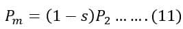
Rotor mechanical output
The ratio of Pc to Pm can be calculated by dividing equations (10) and (11),
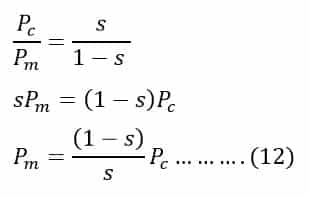
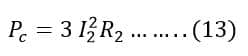
The copper loss in the rotor circuit is;
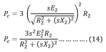
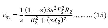
Putting the value of copper loss(Pc) in equation(12) from equation (14), we get
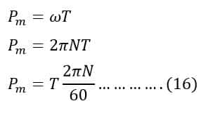
We know,

Therefore,
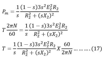
Putting the value of Pm from equation(16) in equation(15), we get;
The slip of an induction motor is expressed by ;
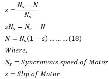
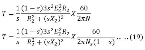
Putting value of N in equation(17), we get;
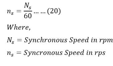
The synchronous speed of the motor(ns) in rps in ns can be given by the following formula.
Putting value of Ns/60 in equation(19), we get;
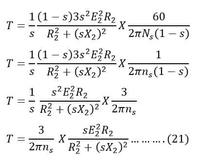
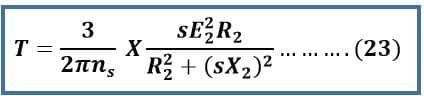
Comparing equations (9) and (21), We get
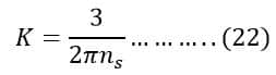
Thus, the torque equation of the induction motor is;
Equation of Starting Torque
When an induction motor starts the slip of the motor is 1.
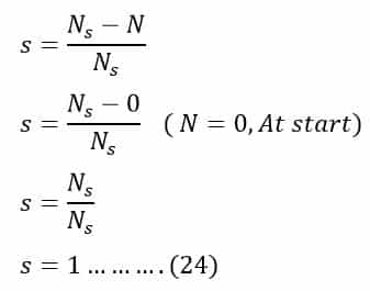
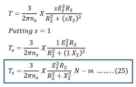
Therefore, the equation of starting torque can be obtained by simply putting the value of s = 1 in the torque equation(23) of the three-phase induction motor,
Starting torque equation of the Induction motor is;
Equation of Maximum Torque
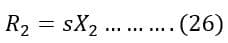
The maximum torque in the induction motor occurs when the rotor resistance(R2) is equal to the product of the slip(s) and the rotor reactance(X2).
The slip(s) at maximum torque occurs is;
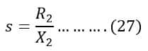
Putting value of slip from equation(27) in the torque equation(23), we get;
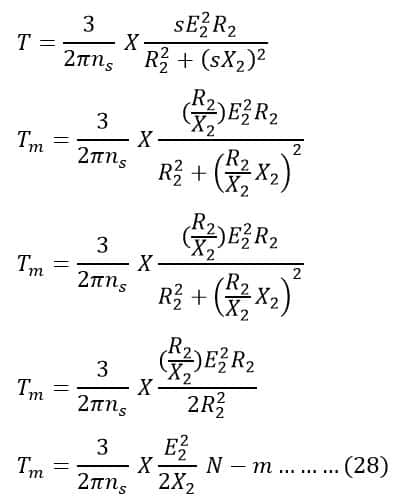
From the above equation, it is clear that if we add external resistance to the rotor circuit it is possible to get the maximum torque at the higher slip. The resistance is cut off gradually with motor acceleration and finally, after the acceleration of the motor up to its rated speed, the rotor resistance is totally cut off. Only, rotor circuit resistance remains in the circuit, similar to the squirrel cage induction motor.
From the above equation(28), we can conclude the followings.
- The maximum torque depends on rotor-induced EMF at the standstill, and it is directly proportional to the square of the rotor-induced EMF.
- The maximum torque is inversely proportional to rotor reactance.
- The maximum torque does not depend on the rotor resistance.
- The slip at which maximum torque depends upon rotor resistance, R2. Therefore, it is possible to achieve the maximum torque at any slip by varying the rotor resistance.
Solved Problems on Torque of Induction Motor
Problem 1: A 3-phase, slip-ring, induction motor with a star-connected rotor has an induced e.m.f. of 120 volts between slip-rings at standstill with normal voltage applied to the stator. The rotor winding has a resistance per phase of 0.3 ohms and standstill leakage reactance per phase of 1.5 ohms.
Calculate the slip and rotor current per phase when the rotor is developing maximum torque.
Solution:
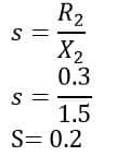
To calculate Slip we must know the relation between resistance and reactance,
As we know, the torque of a rotor under running conditions is
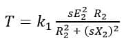
The condition for maximum torque may be obtained by differentiating the above expression with respect to slip s and after differentiating the above equation we will get,
R2 = sX2
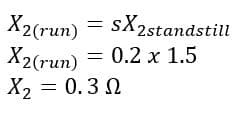
and we also know, for a slip s, the rotor reactance will be s times the reactance at standstill.
We know, for a slip s, the rotor-induced emf will be s times the induced emf at standstill.
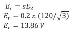
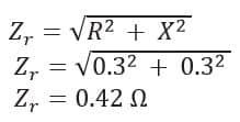
And hence rotor current per phase will be derived as
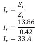
Hence the slip is 0.2 and the rotor current per phase is 33 A.
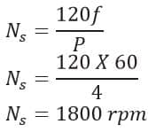
Problem 2: A three-phase, 460V, 100HP, 60Hz, 4-pole induction machine delivers rated output power at a slip of 0.05. Determine rated torque.
Where,
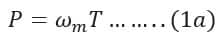
P = Power
ω = Angular Velocity
T = Torque
Where,
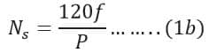
Ns = Synchronous speed
f = Frequency
P = Number of Pole
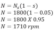
And Rotor/Rated speed will be calculated as,
Now from equation (1a)
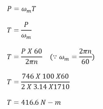
And hence rated torque of the motor is,
T = 416.6 N-m