In this article, we will discuss strain gauge factor derivation. The strain gauge is a passive transducer that converts the strain produced by a force to a change in the resistance.
We will first understand the basic terminology used in the strain gauge.
Stress
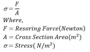
Stress is defined as a restoring force per unit area of any given material. It is denoted by the Greek letter σ, and is measured using Pascal orN/m2.
Stress is mathematically expressed as-
Strain
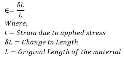
Strain is the amount of deformation experienced by the body in the direction of the force applied, divided by the initial dimensions of the body. The strain is a dimensionless quantity that defines the relative change in shape.
Strain is mathematically represented as:
Strain Gauge
A Strain gauge is a sensor whose resistance will vary when any force is applied. A strain gauge converts force, pressure, tension, weight, etc., into a change in electrical resistance which is then measured.
When any external force is applied to an object, deformation occurs in the shape of the object. The deformation observed in the shape can be both compressive and tensile. This is called strain. This strain is measured by a strain gauge.
Strain Gauge Factor Derivation
The Strain Gauge Factor Derivation is an example of the passive transducer that uses the variation in the electrical resistance in any wires to sense the strain produced by a force on the wires. Resistance strain gauges are also termed piezo resistive gauges.
When any gauge is subjected to positive stress, the length increases while the area of the cross-section decreases. The resistance of the conductor is directly proportional to its length and inversely proportional to its area of the cross-section, so the resistance of the gauge increases with the positive strain. There are many detectors & transducers, e.g. load cells, torque meters, pressure gauges, temperature sensors, etc., that employ the Strain Gauge Factor Derivation as secondary transducers.
The types of strain gauge factor derivations are:
- Unbonded Strain Gauge
- Bonded Strain Gauge
Unbonded Resistance Strain Gauge
The unbonded resistance strain gauge consists of a wire stretched between two points in an insulating medium, such as air. In this type, the strain gauge is not directly bonded to the surface which is subjected to the stress. Instead, the wire is stretched between two frames with the help of insulation pins. The wires are kept under tension so as to avoid sag and/or free vibration. Unbonded Strain Gauge Factor Derivation is usually connected in a bridge circuitry. The bridge is balanced with no load applied to it.
Specifications of unbonded strain gauge
- The typical size is 0.003 mm in diameter and 25mm in length
- Resistance is 120W, 350W to 1000W
- The maximum excitation voltage is 5V to 10V
- Construction material – Nichrome, constantan, nickel
Advantages of unbonded strain gauge
- It has greater accuracy.
- They can be used in the range of ±0.15% strain.
- Disadvantages of unbonded strain gauge:
- They require more space.
Bonded Resistance Strain Gauge
Bonded strain gauges are directly placed or bonded on the surface of any device or component which is subjected to stress. They are divided into 3 different types:
1. Wire Type strain gauge
They are available in bonded and unbonded types. In the bonded type, the strain gauge is directly placed on the surface of the structure under test. To place the strain gauge on the structure, adhesives are used which are responsible for transmitting the strain from the structure to the gauge wires. This type of gauge is basically fabricated in four varieties. They are:
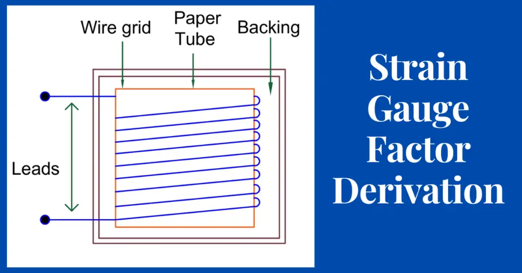
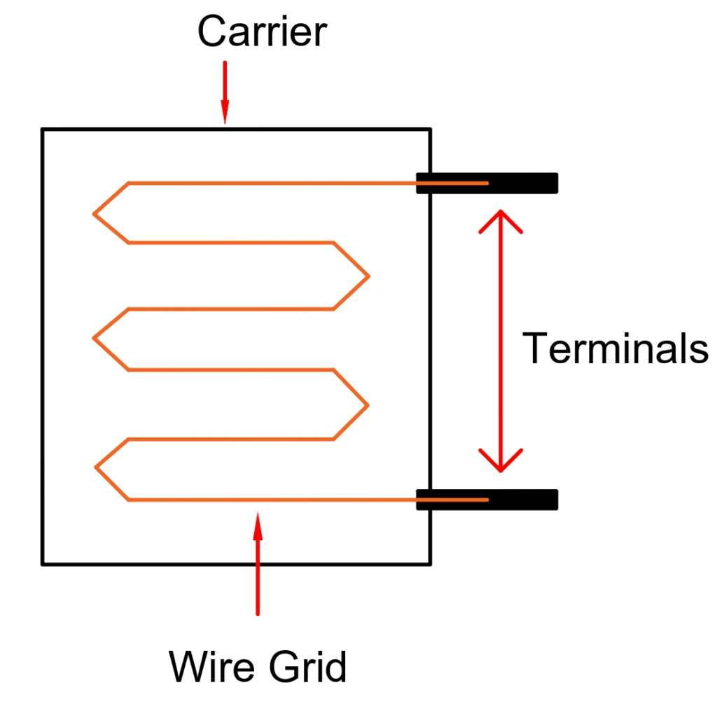
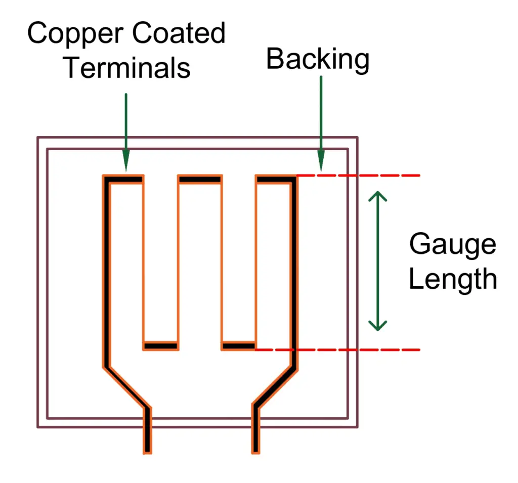
a. Flat grid wire gauge
In the flat grid wire gauges, the fine wire is wound back and forth (i.e., arranged in the form of a grid), and then it is pasted on a backing material (ex: epoxy, paper, etc), with the help of an adhesive.
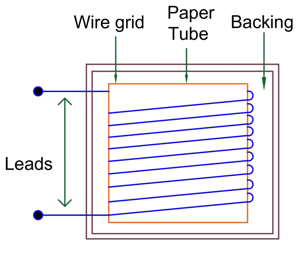
b. Wrap Around Wire Gauge:
In a wrap-around wire gauge, a fine wire is wound on a thin strip or a flattened tube of paper. They can be made smaller in length for the same value of resistance as compared to the flat grid type. In the wrap-around wire gauge type, the wire grid is in between the two planes, the gauge has a very high surface thickness. So, creep and hysteresis increase.
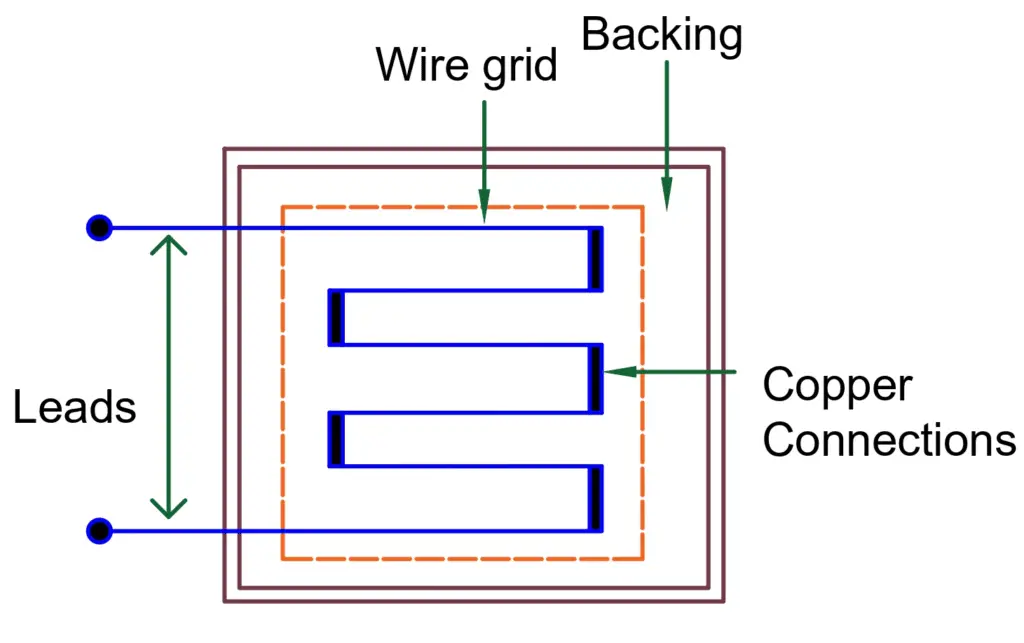
C. Single Wire Gauge
Single wire gauge type of wire gauge is mainly designed to avoid any cross-sensitivity factor. These are formed when the single wires are stretched across and laid as shown below. In order to avoid the looping of the same material, thick copper wires are also attached (welded) at the ends. Due to this, cross-sensitivity is reduced to a great extent.
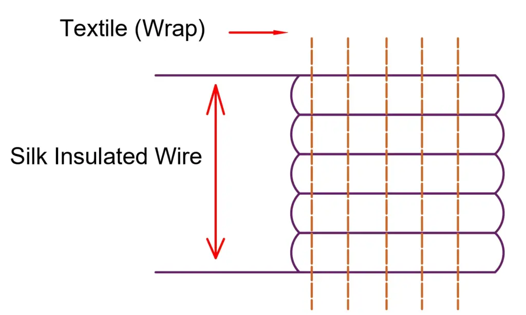
D. Woven Type Gauge
A woven type gauge is formed when a silk-insulated eureka wire is wound as the weft on a textile or rayon wrap. These gauges can measure large strains. They are also used to carry out tests on leather and fabrics.
2. Foil Type strain gauge
Foil gauges differ from wire gauges in construction. In foil gauges, the required grid pattern is formed with a very thin foil which is of the same material that is used for wire gauges. Due to the larger surface area to the area of cross-section ratio, it has a higher heat dissipation capability and so has better thermal stability. The strain reproducibility is excellent.
Specifications of bonded strain gauge
- Typical size = 3mm × 3mm × 3mm, but sometimes bigger than 2.5mm × 12.5mm
- Resistance = 120W to 1000W
- Maximum excitation voltage = 5V to 10V
- Construction materials are Nichrome copper, nickel-chromium, or ferrous nickel alloys.
Advantages of bonded strain gauge
- It has greater accuracy.
- High sensitivity and stability
- Perfect bonding can be done.
- Can measure high pressure.
Disadvantages of bonded strain gauge
- These are sensitive to change in temperature.
Strain Gauge Factor Derivation
We know that
As a result of the strain, two physical parameters are of particular interest.
- The change in gauge resistance.
- The change in length.
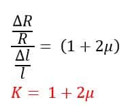
The measurement of the sensitivity of a material to the strain is called the gauge factor (GF). It is the ratio of the change in the resistance ΔR/R by changes in the length Δl/l
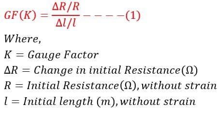
Since strain is defined as the change in length divided by the original length,

Putting the value of strain in equation(1), we get
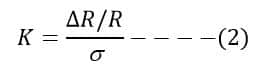
where σ is a strain in the lateral direction.
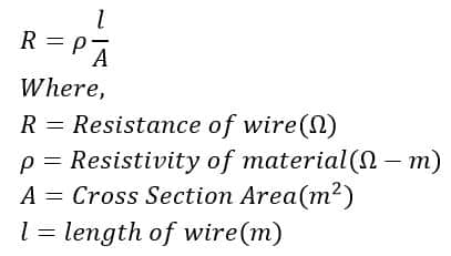
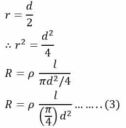
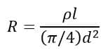
The resistance of the conductor of a uniform cross-section is
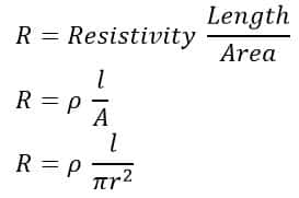
Since
where
- ρ= specific resistance of the conductor
- l = length of the conductor
- d= diameter of the conductor
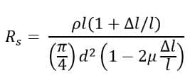
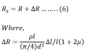
When this conductor is stressed due to the strain, the length of the conductor increases by Δl and simultaneously decreases by Δd in diameter. Hence the resistance of the conductor can be written as
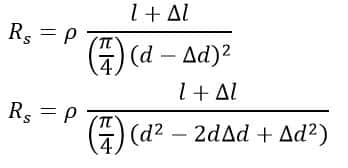
Since Δd is very small, Δd2 can be neglected
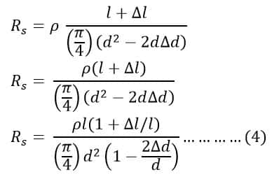
Now as per Poisson’s ratio μ is defined as the ratio of strain in the lateral direction to the strain in the axial direction, that is,
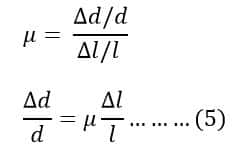
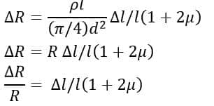
Substituting Value Δd/d from equation (5) in equation (4), we get
By rationalizing the above equation, we get
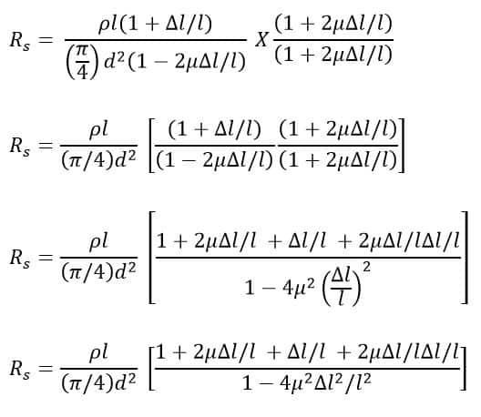
Since Δl is very small, we can neglect the higher powers of Δl.
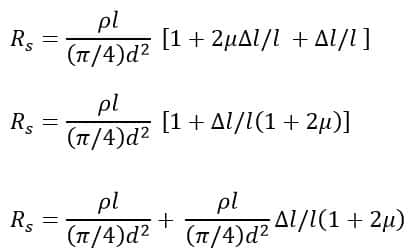
From equation number 3,
Therefore,
The Change in resistance is
Gauge Factor will be