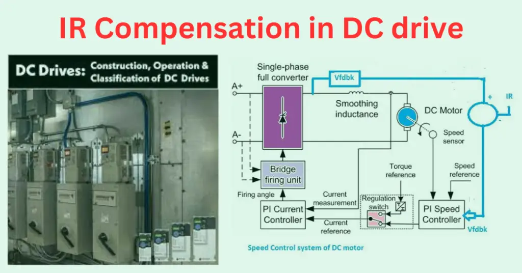
IR compensation is an essential feature in DC drives and VFD to ensure speed regulation, especially when tachometer feedback is unavailable. The following sections explain the working principle, the need for IR compensation, and how it is implemented.
What is IR Compensation?
IR compensation method is used to provide the speed regulation in the DC drive. The DC drive increases the output voltage of the drive to maintain the speed of the drive.
Working Principle of Speed Control in DC Drives
The DC motor’s speed can be precisely controlled through the firing angle of SCRs, which regulate voltage. This forms the basis of the typical DC drive circuit diagram.
In a DC drive, the speed of the DC motor is governed by regulating the DC voltage by controlling the firing angle of the SCRs.
The speed of the DC motor can be given with the following formula.
N=K * Eb /ø = K*( V-Ia* Ra)/ø —–(i)
Where,
N = Speed of the motor,
Eb= Back EMF of motor
Ra= Armature Resistance
Ø= Field Flux
This formula shows that motor speed depends on back EMF, not directly on the applied voltage.
In a separately excited DC motor, the field flux is kept constant.
DC Motor Equivalent Circuit and IR Compensation
Understanding the DC motor equivalent circuit helps explain the need for IR correction. Since the back EMF governs motor speed, and it’s affected by the armature resistance drop, compensating this drop (IR) is necessary.
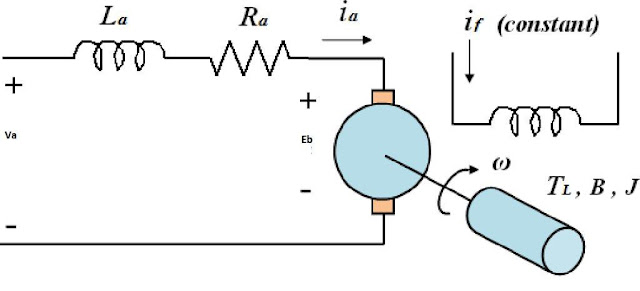
The speed of the DC motor is governed by controlling the armature voltage. The DC drive controls the DC output voltage fed to the DC motor. However, as per equation (1), the speed of the motor is not exactly proportional to the armature voltage; the speed of the motor is proportional to the motor’s back EMF, which is equal to (V- Ia*Ra).
Speed Feedback in Precision Applications
In systems such as weighing machines or conveyors, IR compensation in VFD and DC drives becomes crucial when tachometer feedback isn’t available or fails.
In precise speed control applications like in the weighing system, the RPM of the motor is controlled in the close loop to ensure the desired speed accurately. The motor speed can be measured with a tachometer mounted on the motor shaft that accurately measures the speed.
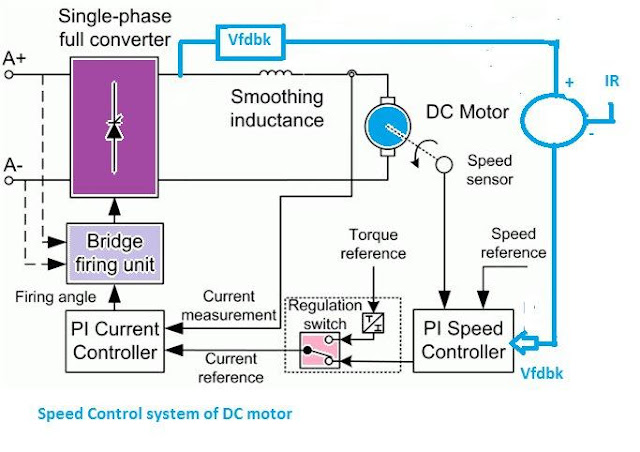
The control scheme of the DC motor with speed feedback arrangement is given below.
Role of Tachometer in Speed Feedback
Tachometer-based feedback is more accurate and eliminates the need for IR comp logic. However, if it fails, the system switches to armature voltage feedback where IR compensation becomes essential.
The speed control of the DC motor can be achieved by controlling the armature voltage by changing the firing angles of silicon control rectifiers (SCRs). The speed of the motor can be measured with the tachometer mounted on the motor shaft or by measuring the armature voltage of the motor.
The measurement with the tachometer gives an accurate measurement of the motor speed. The speed measured through the tachometer is compared with the desired speed reference, and the resultant error signal controls the firing angles of the SCRs.
When the drive runs on tachometer feedback, IR compensation is not required as the drive increases voltage as per the set point of speed.
Switching to Armature Voltage Feedback
If tachometer feedback fails, the system can shift to armature voltage as a speed reference. This triggers IR compensation logic to account for the internal voltage drop in the armature circuit.
If the tachometer voltage feedback circuit fails, the drive system can be smoothly changed from a tachometer to an armature voltage feedback system. The armature voltage feedback as a speed feedback signal is the derived parameter for speed measurement of the DC motor; it does not give the accurate speed of the motor.
Why IR Compensation is Necessary
When using armature voltage feedback, dc IR voltage drop (Ia × Ra) must be subtracted from terminal voltage to determine true back EMF. Without this, speed readings are inaccurate.
The measurement error, as stated above, is because the speed of the motor is directly proportional to the back EMF. The back EMF of the DC motor can be calculated by subtracting the armature resistance drop (Ia*Ra) from the armature applied voltage.
Auto-Tuning and IR Drop Calculation
The drive uses stored motor parameters obtained during auto-tuning to estimate and compensate for IR drop during operation.
The DC drive calculates the IR drop of the motor from the mathematical algorithm stored in its microprocessor. When the motor is first commissioned, the drive must be auto-tuned with the DC drive controller—the drive stores all-important motor parameters during the auto-tuning process.
IR Value of Motor and IR Correction
During auto-tuning, the IR value of motor (based on resistance and current) is stored in the drive’s controller. This allows precise calculation for IR correction when feedback switches to voltage.
When the motor speed control feedback is changed from tachometer to armature voltage, the drive calculates the IR drop of the armature, and the firing angle of the SCRs is reduced to increase the armature voltage to compensate for the IR drop of the armature. When the drive takes armature voltage as speed feedback, the IR compensation is a must to get the desired motor speed.
IR Compensation in VFD
IR compensation in VFD (Variable Frequency Drive) is a technique used to maintain motor torque at low speeds by correcting the internal voltage drop across the stator resistance. Although the term “IR compensation” is more common in DC drives, a similar method is used in VFDs for accurate speed and torque control.
At low speeds, the voltage induced in the motor is low, and the effect of stator resistance (I × R) becomes significant. Without compensation, the motor may not develop enough torque to start or drive the load. IR compensation works by adding a calculated voltage to the output to counter the resistive drop. This ensures that the actual voltage across the motor windings remains adequate for producing torque.
This feature is especially important for applications like conveyors, hoists, and fans, where low-speed torque is critical. Most modern VFDs include this function automatically as part of their vector control or sensorless vector control algorithm.
In summary, IR compensation in VFD improves low-speed motor performance by compensating the internal resistance drop, allowing better torque response, smoother operation, and improved stability.
FAQs
IR compensation is the technique used to maintain correct speed in DC drives or field-oriented VFDs by offsetting the voltage drop due to motor armature resistance.
Although not called IR compensation, modern VFDs use similar voltage compensation techniques for better control under low-speed or high-load conditions.
DC IR refers to the internal resistance drop within a DC motor’s armature that needs compensation for accurate speed regulation.
Realted Artciles: