What is True Power Factor?
The true power factor is the product of the displacement power factor and the distortion power factor. The displacement power factor depends on the phase angle difference between the voltage and current of a linear load. In contrast, the distortion power factor depends on the total harmonic distortion caused by the non-linear loads.
To understand what the true power factor is, let us first discuss the non-linear and linear loads.
Non-linear Loads
Loads, which have non-linear voltage-current characteristics, are called non-linear loads. When connected to a sinusoidal voltage, these loads draw non-sinusoidal current. Modern power electronic systems result in non-sinusoidal current when connected to the sinusoidal voltage source.
Typical non-linear devices are fast static switches like:
- Diode
- Silicon Controlled Rectifiers (SCRs)
- Gate Turn Off Transistors (GTOs)
- Insulated Gate Bipolar Transistors (IGBTs)
- Insulated Gate Commutated Thyristors (IGCTs)
Note: Almost all semiconductor devices are non-linear or non-ohmic. They do not follow Ohm’s law, and the current drawn is not proportional to the applied voltage.
The non-linear devices can be classified under the following three major categories:
🔹 Power electronics:
Rectifiers, variable speed drives, UPS systems, inverters
🔹 Ferromagnetic devices:
Transformer (non-linear magnetizing characteristics)
🔹 Arcing devices:
Arc furnace equipment generates harmonics due to the non-linear characteristics of the arc itself.
Consumers predominantly generate the harmonics, and the utility stands to be affected, as do the other consumers connected to the system. The closest example one can cite is that of passive smoking.
Important: The harmonic amplitude generated by transformers, motors, and generators is usually insignificant compared to power electronics and arcing equipment, unless magnetic core saturation occurs.
Harmonic voltages affect the performance of other equipment connected to an electrical network.
Total Harmonic Distortion ( THDv & THDi)
The Total Harmonic Distortion in voltage (THDv) and current (THDi) is the square root of the sum of squares of the individual harmonic voltage from harmonic order 2 & onwards (Higher-order may be neglected as their magnitude is low)
THDv = √(V₂² + V₃² + V₄² + V₅² + …)
% THDv = (THDv / V₁) × 100, where V₁ = Fundamental Voltage
THDi = √(I₂² + I₃² + I₄² + I₅² + …)
% THDi = (THDi / I₁) × 100, where I₁ = Fundamental Current
Note: The even-order harmonics are absent if the current waveform is symmetrical about the x-axis.
The total harmonic distortion in voltage (THDv) and current (THDi ) is the square root of the sum of squares of the individual harmonic voltage from harmonic order 2 & onwards ( Higher-order may be neglected as their magnitude is low )
For more detail: Read- Total Harmonic Distortion(THD) & Its Measurement
Difference between True Power Factor and Displacement Power Factor
The linear devices draw sinusoidal current from the sinusoidal supply source, which does not distort the current waveform. Equipment like an inductor, induction motor, and transformer are examples of linear devices.
This equipment also consumes magnetizing current for its operation. The current drawn by this equipment is sinusoidal, but the current waveform is not in phase with the voltage.
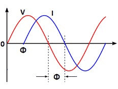
The cosine of the phase angle difference between voltage and current is called the displacement power factor (DPF) or the fundamental power factor.
The semiconductor devices draw the current in phase with the applied voltage. However, the current is not sinusoidal. The non-sinusoidal current generates harmonics in the electrical network.
The measurement of the harmonics is checked by calculating Total Harmonic Distortion (THD).
The harmonic current is also a reactive current, which does not contribute to active power delivery.
The power factor due to non-linear current drawn from a sinusoidal supply source is known as the distortion power factor.
True Power Factor = Displacement Power Factor × Distortion Power Factor
Let us understand both terminologies of power factor in detail for linear and non-linear loads.
Power Factor of Linear Loads
When the loads connected to the system are linear, and the sinusoidal voltage is applied to the load, the load draws the sinusoidal current. The cosine of the phase angle between the voltage and current is known as the displacement power factor.
🔹 Displacement Power Factor Formula:
Pf = CosΦ
Where Φ is the phase angle between voltage and current.
The displacement power factor shows that the equipment draws reactive energy for its operation.
In the case of a resistive load, there is no phase angle difference between voltage and current as the resistance does not consume reactive energy.
- The fundamental and the distortion power factor for resistive load is unity.
- Power Factor = Active Power / Apparent Power
The power factor is the cosine of the angle between the voltage and the current. The power factor with linear loads is known as the displacement power factor. Why is this phase displacement between voltage and current? The phase difference between voltage and current shows that the equipment draws reactive energy for its operation.
In the case of the resistive load, there is no phase angle difference between voltage and current as the resistance does not consume the reactive energy. The fundamental and the distortion power factor for resistive load is unity. The displacement power factor can be calculated by measuring the active and apparent power. The power factor formula is given below.
Power Factor = Active Power/ Apparent Power
Let’s take the example of an induction motor to understand the displacement or fundamental power factor better. The induction motor uses a magnetizing current to work. The magnetizing current lags the applied voltage by 90 degrees electrical. That is why the total current drawn by the motor is always more than the active current drawn by the motor.
In such cases, although the current remains sinusoidal (since the load is linear), the presence of this phase difference reduces the displacement power factor.
This is typical in inductive equipment like motors, transformers, and chokes, where improving displacement power factor requires power factor correction capacitors.
Summary: In linear loads like resistors, power factor = 1 (ideal). In inductive linear loads, power factor < 1, mainly due to phase shift (not harmonics).
Power Factor of Non-linear Loads
When the loads connected to the system are non-linear, the equation of the power factor of the linear loads is not valid, and one more concept of distortion power factor is taken into account for calculating the true power factor.
The semiconductor devices like a diode, Bipolar Junction Transistor, and Insulated Gate Bipolar Transistor(IGBT) are examples of non-linear loads. The non-linear loads generate harmonics, and the harmonic current is reactive. The current drawn by the non-linear devices is not sinusoidal, and it distorts the fundamental current waveform. The power factor deteriorates with an increase in the harmonics distortion.
In non-linear systems, harmonics are the major contributors to power quality issues and poor power factor. These harmonics distort the waveform and reduce efficiency.
The power factor with non-linear loads is known as the distortion power factor.
Distortion Power Factor
The non-linear devices( All the semiconductor devices) draw non-sinusoidal current from the sinusoidal source. According to the Fourier Series, the non-sinusoidal current can be resolved into the fundamental and integral multiples of the fundamental current. The integral multiples of the fundamental current are the harmonic current that produces the distortion in the electrical network.
Distortion power factor = 1 / (√ 1 + THD²ᵢ)
Lower THD means higher distortion power factor. Maintaining THDi under limits is crucial for improving the true power factor.
True Power Factor
The overall power factor of the electrical network depends not only on the displacement power factor but also on the harmonic distortion in the electrical network.
The true power factor is calculated using the following formula:
True power factor = Displacement power factor × Distortion Power factor
= CosФ × 1 / (√ 1 + THD²)
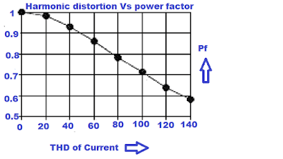
The true power factor deteriorates with an increase in harmonic distortion. The table below shows how the overall power factor(True power factor) is low even if the displacement power factor is 0.9.
This demonstrates that even when voltage and current are in phase (good displacement PF), harmonics can still degrade the total system efficiency.

Example: In the case of the VF drive, the displacement power factor is unity; however, the true power factor may be in the range of 0.996 to 0.998.
How to Improve True Power Factor?
The True Power Factor can be improved by improving the displacement and distortion power factors.
1. Improvement of Distortion Power Factor
The harmonics are generated due to non-linear loads like variable frequency drives, soft starters, Slip power recovery systems, etc. Harmonics can’t be eradicated but can be mitigated so that harmonic current does not flow in the electrical network. There are several methods of harmonics mitigation techniques. Some of the methods are
a. Installation of Harmonic Filter
Tuned or de-tuned filters can be installed to mitigate harmonics in the electrical network. The Active Filter is also a solution for mitigating harmonics.
Active filters are dynamic and adaptive, making them highly effective for fluctuating harmonic environments.
b. Installation of 12 Pulse Rectifier
The harmonics generated in the system depend on the number of pulses. The following formula expresses the harmonic order.
n= PK+/-1
where,
n= Harmonic order
P= Number of pulses
K= integral Value 1,2,3,4………
For 6 pulse rectifier, harmonic order(n) is 6*1+/-1=5,7. The order of harmonics for the 6 pulse rectifier is 5,7,11,13,17,19….. The order of harmonics for the 12 pulse rectifiers is 11, 13, 23, and 25. The harmonic current gets reduced if the rectifier is selected for more pulses.
Increasing pulse number directly reduces harmonic distortion, improving distortion and true power factor.
Read More: Harmonics Mitigation Techniques
2. Improvement of Displacement Power Factor
The displacement power factor depends on the phase angle difference between the voltage and current. The inductive loads draw the magnetizing current, which lags the voltage. To nullify the effect of lagging current, the capacitor is installed, drawing the leading current. Thus, the net current reduces as the capacitor current is in the phase opposition with the lagging current.
Power factor correction capacitors and synchronous condensers are standard equipment for displacement power factor improvement.
Related Articles:
thks learned a lot
But how did you get the true power in the table? It seems incorrect.
Thanks.
Thanks for the simplified explanation.