Definition- The crest factor, also known as the peak factor, is the ratio of the peak value to the root mean square (RMS) value of an AC quantity. It is an important parameter in electrical engineering that indicates how much an AC waveform peaks compared to its RMS value. A high crest factor signifies sharp peaks in the waveform, which can impact power quality and equipment performance, such as in power supplies and audio signal processing.
What is Crest Factor?
Any periodic waveform varies in magnitude over time. In the case of direct current (DC), the voltage or current remains constant. However, alternating current (AC) fluctuates continuously, reaching a peak value before decreasing again. Since AC waveforms do not maintain a steady magnitude, engineers use specific parameters, such as peak value and root mean square (RMS) value, to analyze their characteristics.
The crest factor quantifies the sharpness of waveform peaks. It is defined as the ratio of the peak value to the RMS value of an AC waveform. A higher crest factor indicates sharper peaks, which can impact power quality, electronic circuit design, and signal processing. For instance, a pure sine wave has a crest factor of approximately 1.414, whereas a square wave has a crest factor of 1. By understanding the crest factor, you can assess the efficiency and potential distortion in electrical systems
Crest Factor Formula
The crest factor (CF) of a waveform is the ratio of its peak value (Vpeak) to its root mean square (RMS) value (VRMS). Mathematically, it is expressed
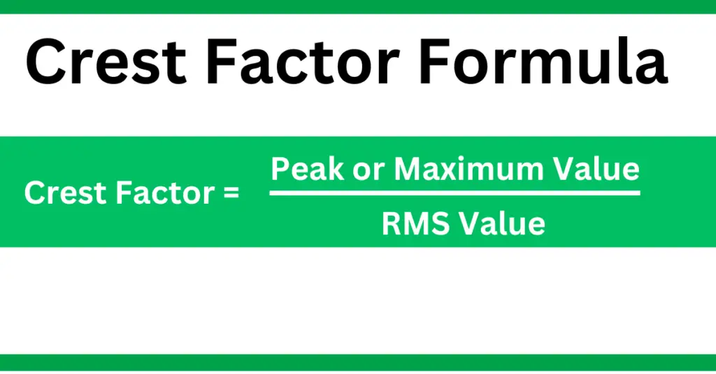
For example, a pure sine wave has a crest factor of approximately 1.414, while a square wave has a crest factor of 1.0. A higher crest factor indicates sharper peaks, which can affect power quality and circuit performance in electrical and signal processing applications.
Crest Factor Formula Derivation
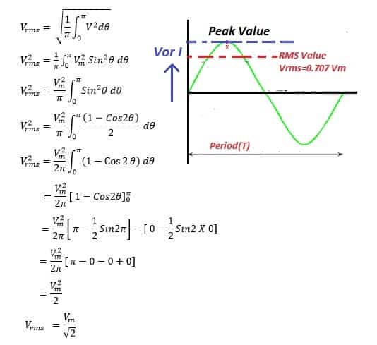
To determine the crest factor, we need to calculate the RMS value of AC.
The root mean square (RMS) value of an alternating current (AC) is the equivalent DC value that produces the same heating effect in a resistive load. In other words, an AC source with an RMS voltage of 230V delivers the same power to a resistive load as a 230V DC source.
For a perfect sinusoidal AC waveform, the RMS value is related to the peak (maximum) value as:
The crest factor of a sine wave can be mathematically expressed as;
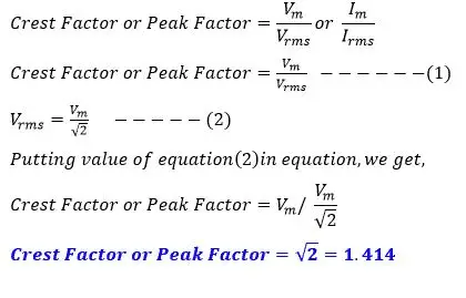
The crest factor of a sine wave is 1.414.
Crest Factor of Various Waveforms
Various waveforms have different crest factors, affecting their performance in electrical and signal processing applications. The table below summarizes the crest factors for common waveforms:
| Waveform | Crest Factor(CF) | Formula |
| Sine Wave | 1.414 | CF=Vrms/Vpeak= √2 |
| Square Wave | 1.0 | CF=Vrms/Vpeak= 1 |
| Triangle Wave | 1.732 | CF=Vrms/Vpeak= √3 |
| Sawtooth Wave | 1.732 | CF=Vrms/Vpeak= √3 |
| Half-wave Rectified Sine Wave | 2.0 | CF=Vrms/Vpeak= 2 |
| Full-wave Rectified Sine Wave | 1.414 | CF=Vrms/Vpeak= √2 |
Key Insights:
- Higher crest factors (sine, triangle, and sawtooth waves) indicate larger peak values for their RMS values, which may affect power quality.
- A crest factor of 1 (square wave) suggests a steady waveform, making it ideal for digital signals.
- Engineers use crest factors to analyze waveform characteristics in power systems, audio processing, and circuit design.
Why Crest Factor is Crucial for UPS Selection?
When selecting a UPS, it’s essential to consider the crest factor to ensure the system can handle short-term peak loads without tripping or overloading. For example, if a load has a crest factor of 3:1, a UPS rated for 3 kVA may need to handle up to 9 kVA to accommodate these transient peaks effectively. UPS systems with a high crest factor tolerance are vital for equipment like motors, computers, and industrial machinery, where power fluctuations are common.
Comparing the Crest Factor of Sinusoidal and Non-Sinusoidal Currents
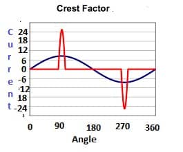
From the above figure,
Crest Factor of a sinusoidal waveform
Crest Factor= I peak/ Irms= 8.20/5.8=1.414
Crest Factor of non-sinusoidal waveform
Crest Factor= I peak/ Irms= 24.2/5.8=4.17
A sinusoidal waveform has a fixed Crest Factor of 1.414, indicating a smooth and predictable peak-to-RMS ratio. In contrast, a non-sinusoidal waveform exhibits a much higher Crest Factor (4.17 in this case), signifying greater peak values relative to its RMS value. This increased Crest Factor in non-sinusoidal waveforms is often associated with power quality issues, harmonics, and potential stress on electrical equipment.
Significance of Crest Factor in Electrical
The crest factor is a crucial parameter in electrical engineering, influencing power system design, equipment selection, and power quality analysis. It represents the ratio of peak value to RMS value of a waveform and plays a significant role in various applications. Below are key areas where the crest factor holds importance:
1. Power Supply Capacity Selection
The rating of a power supply must be determined based on the peak current demanded by the load. Loads with higher crest factors require power supplies with a much higher capacity or require de-rating to prevent overloading. For instance:
- If an electronic device draws a higher peak current relative to its RMS value, the power supply must be capable of handling those peaks without distortion or failure.
- In industrial applications, power supplies for variable frequency drives (VFDs) and inverters must be carefully selected to avoid excessive stress on the components.
2. Current Transformer (CT) Selection
The crest factor is crucial when selecting current transformers (CTs) for accurate measurements. If the peak current is too high, metering CT inputs may clip, leading to inaccurate readings. To ensure proper CT selection:
- A load with 15A RMS and a crest factor of 4.0 will have a peak current of 60A. A 20A CT would be inadequate because it would not accurately capture the peak values.
- The maximum RMS current for accurate measurement depends on the crest factor and is often expressed as a percentage of the CT’s rated current.
- If the crest factor is unknown, it is generally assumed to be in the range of 1.4 to 1.5, and a CT rating of 150% of the expected RMS current is recommended.
3. Impact on Circuit Protection Devices
Protective devices such as fuses, circuit breakers, and relays must be selected considering the crest factor:
- A higher crest factor load may require oversized protection devices to handle peak currents without tripping.
- Low crest factor loads, such as resistive heating elements, have more predictable peak currents and require less conservative sizing.
- Power quality monitoring systems often rely on crest factor analysis to detect potential faults or transient events.
4. Power Quality Analysis
The crest factor provides insight into waveform distortion and power quality issues:
- A crest factor of 1.414 indicates a perfect sinusoidal waveform.
- A crest factor significantly higher than 1.414 suggests waveform distortion, such as the presence of harmonics or transient spikes.
- A crest factor lower than 1.414 may indicate a flat-topped voltage waveform, which can cause inefficient operation of electrical equipment.
5. Energy Efficiency and Transformer De-Rating
High crest factor waveforms can impact transformers and overall system efficiency:
- Power transformers must be de-rated when supplying loads with high crest factors to prevent overheating.
- The Computer and Business Equipment Manufacturing Association (CBEMA) recommends de-rating transformers based on the crest factor to ensure reliable operation.
- Total Harmonic Distortion (THD) and crest factor are closely related, and higher distortion often leads to increased energy losses.
Read Next:
1 thought on “Crest Factor: Definition, Formula and its Significance”