The transposition of conductors in transmission line ensures that each conductor occupies every possible position (top, middle, bottom) at some point, balancing out inductance and capacitance over the entire transmission path.
What is Transpostion of Conductors?
Transposition of conductors is a technique used in high-voltage transmission systems where the physical positions of the phase conductors are systematically rotated along the length of the line.
The goal of transposition is to eliminate the effects of asymmetry, which can otherwise result in voltage imbalances, signal interference, and power losses.
Why is Transposition of Conductors Necessary?
In overhead transmission lines, the three conductors (R, Y, and B phases) are usually not spaced symmetrically. Due to physical constraints such as tower design or terrain, the spacing between conductors varies, which leads to different inductive and capacitive reactance for each phase.
This uneven spacing causes:
- Unequal voltage drops across phases
- Electromagnetic interference (EMI) with nearby communication lines
- Increased line losses and power quality degradation
Without transposition, a phase that remains on the top or side position along the entire route may experience more exposure to mutual inductance from adjacent conductors or external elements. Over long distances, this imbalance grows more significant and may compromise the reliability of the grid.
Transposition equalizes the average electrical parameters of each phase over the full length of the line, thus improving voltage symmetry and minimizing electromagnetic interference.
How Transposition Works
The transposition method involves dividing the transmission line into three equal segments. In each segment, the conductors switch places in a specific pattern to ensure that over the entire length of the line, each conductor experiences every possible relative position.
This method achieves balanced line parameters by symmetrically exposing each conductor to the electrical environment of the others.
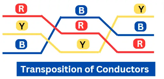
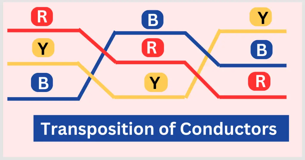
The figure below illustrates the conductors’ transposition cycle.
Example:
In a three-phase system:
- First Segment: R – Top, Y – Middle, B – Bottom
- Second Segment: R – Middle, Y – Bottom, B – Top
- Third Segment: R – Bottom, Y – Top, B – Middle
By the end of the third segment, all conductors have rotated through each position.
This transposition cycle is implemented at substations, switching yards, or by using special transposition towers designed to redirect and rearrange the conductor layout.
Table: Conductors Transposition for R-Y-B Phases
| Segment of Line | R Phase Position | Y Phase Position | B Phase Position |
|---|---|---|---|
| First 1/3rd of the line | Top | Middle | Bottom |
| Second 1/3rd of the line | Middle | Bottom | Top |
| Final 1/3rd of the line | Bottom | Top | Middle |
This arrangement ensures that each phase has equal exposure to the physical layout, neutralizing voltage and inductive differences.
Advantages of Transposition of Conductors
Balanced Inductance and Capacitance
Each phase conductor is subjected to all spatial positions, leading to uniform inductance and capacitance. This helps in maintaining consistent voltage levels across phases.
Reduced Electromagnetic Interference
When line parameters are unbalanced, EM fields are stronger and may couple into nearby telecom lines. Transposition reduces this inductive coupling, minimizing noise and communication disruption.
Improved Voltage Regulation
Voltage drops across long lines are more predictable and equal when conductors are transposed, improving overall voltage regulation and power delivery accuracy.
Lower Transmission Losses
By equalizing the current paths and reducing asymmetrical loading, transposition also helps to reduce transmission line losses and enhance system efficiency.
Drawbacks of Conductor Transposition
Despite its technical benefits, transposition has some practical limitations:
- Structural Complexity: It requires specially designed transposition towers or switching setups that add to the design complexity.
- Higher Installation Costs: Additional materials and labor are needed, especially for high-voltage lines.
- Inspection and Maintenance Challenges: Complex layouts may demand more sophisticated maintenance efforts.
However, in long-distance, high-voltage networks, these costs are justified by the performance improvements transposition provides.
Conclusion
In high-voltage power systems, transposition of conductor in transmission line is not optional — it is a practical necessity. It ensures electrical balance, reduces interference, and improves the efficiency and reliability of the entire grid.
By systematically rotating the positions of R, Y, and B phases, engineers can maintain equal exposure to mutual electrical effects. This eliminates voltage imbalances, reduces EMI, and protects sensitive communication lines.
Though it adds design complexity, conductor transposition is a proven engineering practice that plays a critical role in modern power transmission infrastructure
Frequently Asked Questions (FAQs)
To balance the inductance and capacitance of each phase in a transmission line and reduce electromagnetic interference.
Typically, no. It is mostly used in high-voltage transmission lines where the impact of imbalances is more significant. Transposition isn’t used in distribution lines because they’re short and low-voltage, so imbalance effects are minimal and don’t justify the added cost.
Yes, it helps maintain equal voltage levels across all phases by balancing impedance.
At designated intervals along the transmission line—commonly at substations or using transposition towers.
Transposition of a 3-phase transmission line helps balance inductance and capacitance across all phases, reducing EMI, voltage imbalance, and transmission losses.
Related Articles: