10 different duty cycles of motor are S1, S2, S3, S4, S5, S6, S7, S8, S9, and S10. Asynchronous motors are widely used in households and heavy machinery industries. In this article, we will study different types of load cycles for an asynchronous motor at constant and varying loads with the speed of rotation of the motor. Let’s start!
What is the load Cycle (Duty Cycle) for Motors?
The term duty for machines indicates how hard machines have to work (drive a specific load) and for how long time. It includes the time of starting, stopping, and rest period for machines.
The duty cycle defines the pattern of cycles for a machine, such as starting, stopping with brakes, and running with no load. Shortly, it is the ratio of when machines are on and when machines are off. For instance, a 100% duty cycle motor can run continuously without any rest, while a 50% duty cycle motor can only run for 50% of the entire cycle, which means it can run for 30 seconds and then needs to rest for 30 seconds.
The cyclic duration factor is the percentage ratio between the period of loading and the total duration of the duty cycle.
We will discuss the different duty cycles of a motor in detail in the following sections.
Table of contents
- What is the load Cycle (Duty Cycle) for Motors?
- Continuous Running Duty Cycle(Type S1):
- Short Time Duty Cycle (Type S2):
- Periodic Time Duty Cycle(Type S3 to S8)
- Intermittent Duty Cycle(Type S3):
- Intermittent Periodic Starting Duty(Type S4):
- Intermittent Periodic Duty with Braking(Type S5):
- Continuous Operation Periodic Duty Cycle(Type S6):
- Continuous Operation Periodic Duty with Breaking Duty Cycle(Type S7):
- Continuous Operation Periodic Duty with Related Load or Speed(Type S8):
- Non-Periodic Duty cycle(Type S9):
- Discrete Duty Cycle with Constant Load(Type S10):
- Conclusion
Continuous Running Duty Cycle(Type S1):
In this duty cycle state, motors are designed for a long run without stopping or resting for a long period of time. This duty cycle allows the machine to achieve the state of thermal equilibrium, exerting a constant load for a specific period. Thermal equilibrium is achieved in two systems when the heat flow from high temperature to low temperature of two systems is balanced at a point. S1 indicates this type, and the manufacturer should define the rating at which this motor can operate.
Here is the temperature equilibrium waveform diagram below:
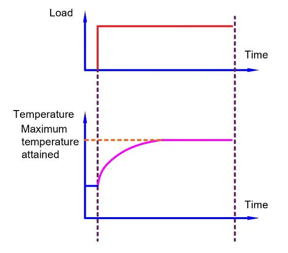
Here, △T represents the change in temperature from state 1 to state 2 to achieve the thermal equilibrium.
Load wave represents time to drive load for a long period of time.
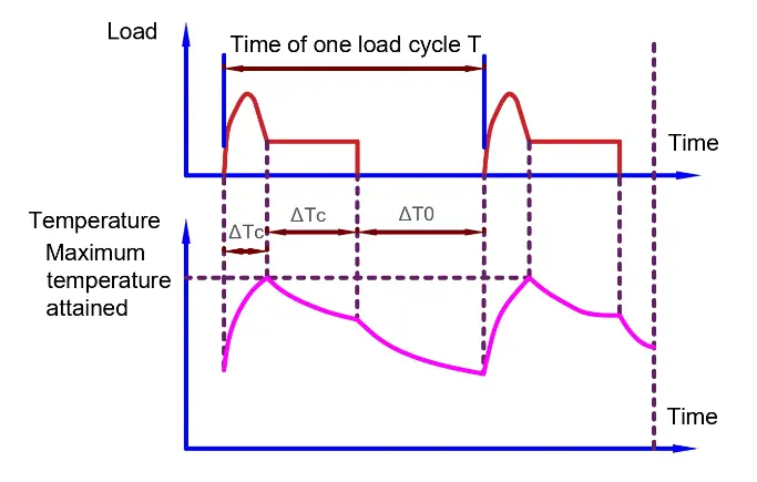
Short Time Duty Cycle (Type S2):
This duty cycle for a machine means that the motor has to drive load for a short period and needs resting time after running time. The motor may be designed to run for 40 minutes and rest for 40 minutes to cool down the machine, and this process will continue with continuous braking for applications that need less running time to drive load. This is called a periodic time-periodic process, and it is always less than the time to achieve the thermal equilibrium. The rating for this type is specified for the limited period for which the motor can drive a constant load, and the S2 type duty represents it. The waveform diagram for this short time duty cycle:
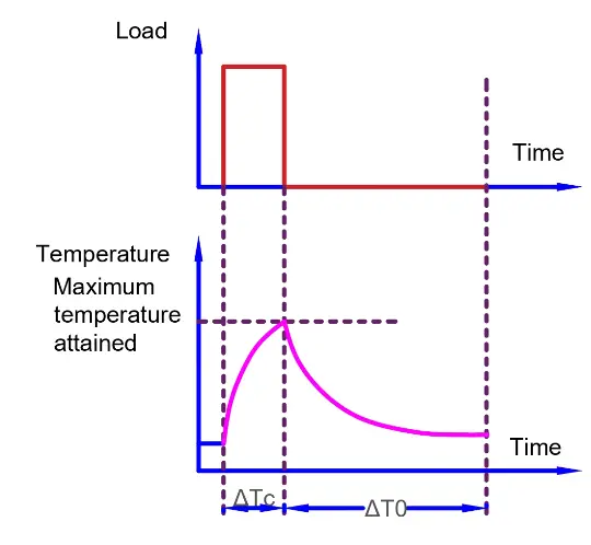
Here,
△TC Indicates the period at constant temperature (room temperature where the machine is driving the load).
△T0 indicates the resting time for cooling down the process before reaching thermal equilibrium in an asynchronous motor.
Periodic Time Duty Cycle(Type S3 to S8)
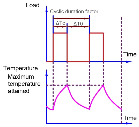
This duty cycle indicates how a machine drives load for repeating periods with work activity and rest time. Meanwhile, there is a ratio of on time (when the motor is running) to the total duty cycle time when the machine is on and off for a specific time, called the cyclic duration factor. A 50% cyclic duration factor indicates that the machine is running for half time and stopping for another half time.
Cyclic Duration Factor Formula: △Tc/T
Here,
T = Total Duty Time
△Tc= Time of running at a constant load
Intermittent Duty Cycle(Type S3):
This type is indicated by S3, and in the duty cycle, the motor operates intermittently for driving load and resting. Let’s try to understand this in easy words:
- Intermittent Duty: In this state, the motor does not run continuously but works (on time) and stops in repetitive behavior.
- Periodic duty: In this state, the motor does not run randomly but runs continuously.
This is the difference between intermittent time and periodic time, as you can see in the following waveform of the intermittent duty cycle.
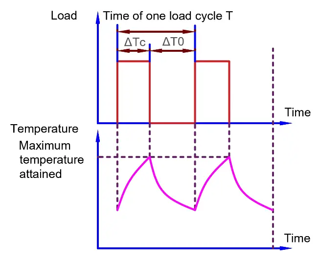
Here,
–△Tc indicates the period at a constant temperature to drive a constant load for work completion.
–△T0 indicates the resting time for the motor.
Intermittent Periodic Starting Duty(Type S4):
This type indicates the motor running for the same duty cycles for on time (starting and working) and off time (resting time). Here is the waveform for the load and motor running duty cycle:
△T* indicates the starting time.
So, for this type, we can write the cyclic duration factor formula as follows:
=(△T*+△Tc)/T
Where △Tc is the time of running at constant load.
Intermittent Periodic Duty with Braking(Type S5):
This is the same as the previous concept with an addition of electric braking in between the on-time and off-time for rest. This is an S5 duty type, and it has the following waveform for the complete cycle:
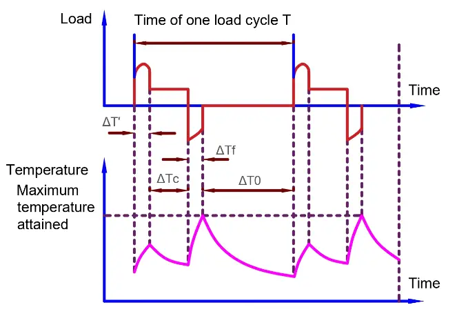
Where △Tf = Time of electric braking
So, for this type, we can write the cyclic duration factor formula as follows:
=(△T*+△Tc+△Tf)/T
Where
△Tc = on time as a constant load
△T0 = off time or resting time
Continuous Operation Periodic Duty Cycle(Type S6):
This is an S6 type of load cycle with a motor running at a constant load under no load conditions. It has no resting time as the motor runs at both loads and no-load conditions.
So, for this type, we can write the cyclic duration factor formula as follows:
= △Tc/T0
Where
T0 = no load condition and,
△Tc= motor running at constant load
Continuous Operation Periodic Duty with Breaking Duty Cycle(Type S7):
This is an S7 type for asynchronous motors, running with constant load and no-load condition with an addition of electric braking application in their duty cycle.
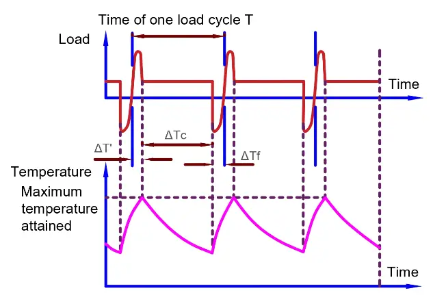
Where △Tf = Time of electric braking
Here,
△T* indicates the starting time
△Tc= motor running at constant load
Cyclic duration factor =1 as running time is equal to the entire cycle duration. In other words, the motor runs continuously while resting.
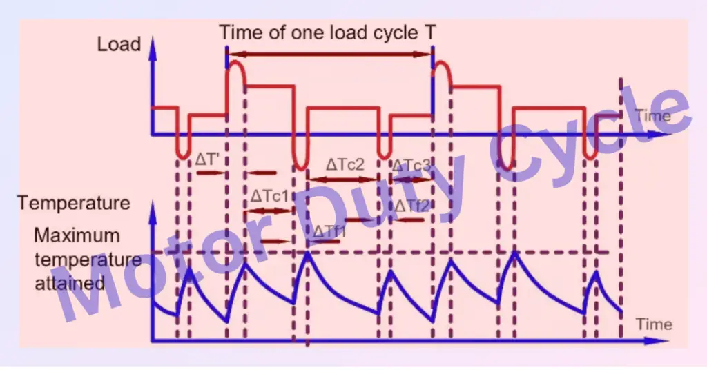
Continuous Operation Periodic Duty with Related Load or Speed(Type S8):
In this type of duty cycle, there are steps of the same duty cycle with a constant load driven by a motor with varying speeds. The load of the motor that has to be driven by the motor or the speed of the motor varies. It has no rest time and falls under the S8 duty cycle type.
The moment of inertia for load and moment of inertia for the machine are both combined in this type at different speeds of rotation. Here is the waveform for continuous operation periodic with related load or speed:
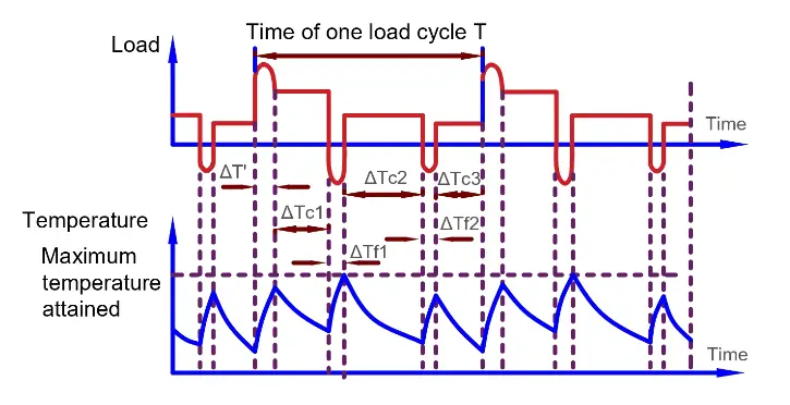
Here △T* indicates the starting time
Where
△Tf1 and △Tf2= Two times of electric braking
△Tc1,△Tc2, and △Tc3= motor running at 3 different constant loads
S8 duty motors have three cyclic duration factors as follows.
=(△T+△TC1)/T ; (△Tf1+△TC2)/T; (△Tf2+△TC2)/T;
Non-Periodic Duty cycle(Type S9):
In this type, no specific patterns for motor operation are present. It lies under type S9 of the duty cycle. Load and speed of rotation for machines both vary non-periodically. Overloading on a motor can lead to this periodic behavior. Here is its waveform:
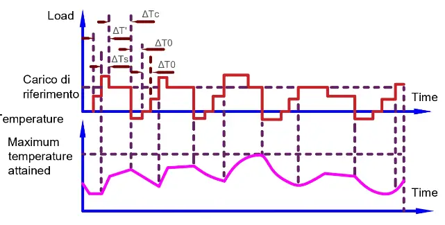
Here △T* indicates the starting time
Where
△Tf1 = Time of electric braking and,
△Tc1= motor running at constant load
△Ts = Overload time
△T0 = off time or resting time
Discrete Duty Cycle with Constant Load(Type S10):
Discrete duty allows the motor to reach a thermal equilibrium state by offering the operation of starting and stopping with specific discrete load values. It starts and stops at specific discrete tie intervals.
The duty type S10 is defined as the operation characterized by a specific number of discrete load values maintained for a sufficient time to allow the machine to reach thermal equilibrium. The minimum load during a duty cycle may have a value of zero, which is relevant to the no-load condition.
A complete designation includes the abbreviation of the duty type, followed by the per unit quantities p/Δt for the partial load and its duration, and the per unit quantity TL, which represents the thermal life expectancy of the insulation system related to the thermal life expectancy in case of duty type S1 with a rated output. Additionally, the quantity r indicates the load for a time when the system is de-energized and at rest. For example: S10 p/Δt = 1.1/0.4; 1/0.3; 0.9/0.2; r/0.1 TL = 0.6.
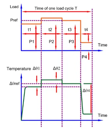
Where,
△θ1;△θ2- Temperature rise difference of the winding at various loads within one cycle compared to the temperature rise based on duty cycle s1 with a reference load.
△θref– Temperature at reference load based on duty type S1 t1: t2: t3: t4 time of a constant load within a cycle P1: P2: P3: P4 time of one load cycle
Conclusion
We have studied various duty cycles of motors for specific time intervals and constant loads. These cycles differ in terms of their starting and stopping times, as well as the application of the braking system. Continuous duty cycles are ideal for machines that need to perform load-driving operations for extended periods. Other types of duty cycles have their own unique waveforms and cyclic duration factors.
When purchasing a motor, it is important to take into account the operational requirements and specify the duty cycle, including maximum and high-duty cycles. This approach ensures that the appropriate motor is selected for desired applications.