Understanding how a BLDC motor controller works is crucial for engineers and developers working in electric vehicles (EVs), robotics, drones, HVAC systems, and industrial automation. A Brushless DC (BLDC) motor cannot operate by simply connecting it to a DC supply — it needs an intelligent electronic controller that sequences current flow to its stator windings at precise timings.
This controller acts as the “brain” of the motor, determining which coil to energize, when to energize it, and how much current to supply — ensuring smooth rotation, torque generation, and efficiency. In this guide, we’ll explore the engineering principles, components, and algorithms behind modern BLDC controllers and their real-world applications.
From Brushed to Brushless: The Evolution of Motor Control
Traditional brushed DC motors used physical brushes and a commutator to switch current direction. While simple, these components led to mechanical wear, sparking, and maintenance issues. The shift to brushless motors eliminated mechanical commutation, replacing it with electronic switching.
Advantages of BLDC Motors:
- Higher efficiency: Minimal energy loss due to absence of friction.
- Longer lifespan: No brushes to wear out.
- Precise control: Electronic feedback allows dynamic speed and torque regulation.
- Smart compatibility: Works seamlessly with automation, IoT, and embedded systems.
This transition required not only motor redesigns but also advanced BLDC motor controllers capable of digitally generating commutation sequences.
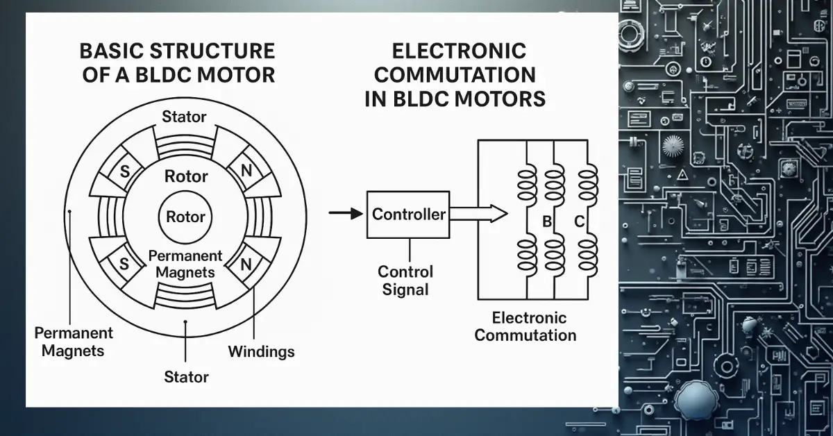
Basic Structure of a BLDC Motor
A BLDC motor is a type of synchronous motor that operates on electronic commutation. It consists of:
- Rotor: Permanent magnets attached to the rotating shaft.
- Stator: Three-phase windings (A, B, C) fixed in place.
- Windings: Energized sequentially to create a rotating magnetic field.
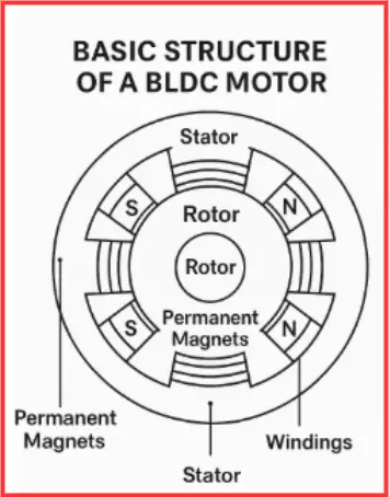
The BLDC controller applies voltage pulses in a precise order so that the stator’s magnetic field continuously aligns with the rotor magnets, creating torque. This precise switching replaces the mechanical commutation of brushed motors.
Why BLDC Motors Need Electronic Commutation
Unlike brushed motors, a BLDC motor depends on semiconductor switches such as MOSFETs or IGBTs to control current flow. The controller must decide:
- Which winding to energize.
- In what sequence.
- How much current to deliver based on torque demand.
Types of Commutation:
- Six-step trapezoidal control: Simple and efficient for general applications.
- Sinusoidal or Field-Oriented Control (FOC): Provides smoother torque and better performance.
These methods ensure precise torque production, reduced acoustic noise, and enhanced efficiency.
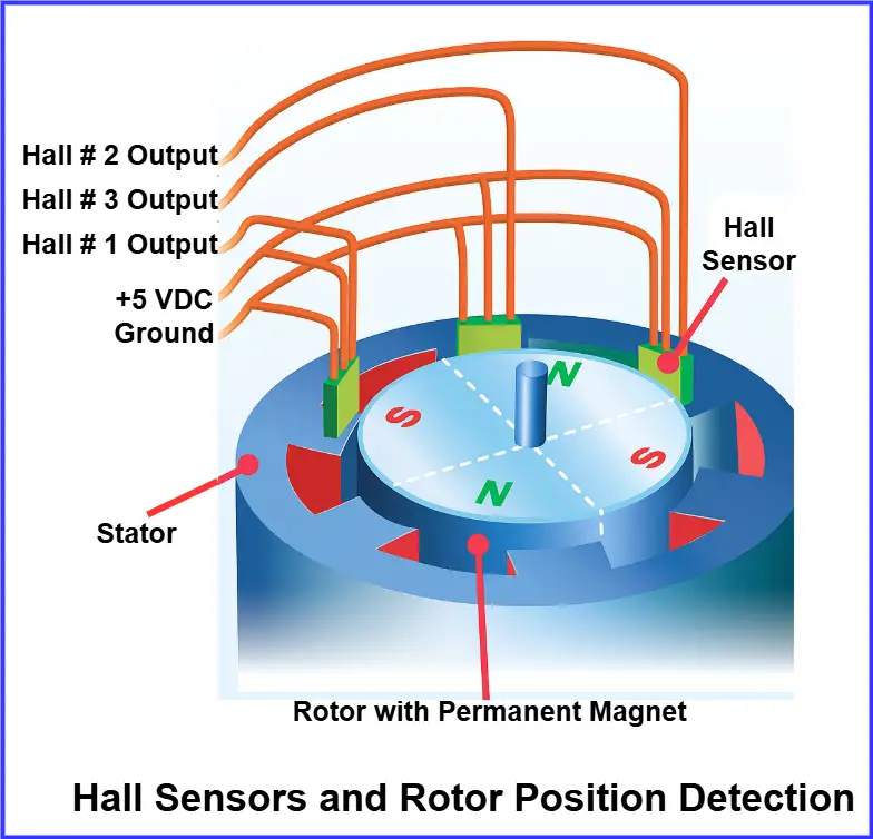
Hall Sensors and Rotor Position Detection
In sensor-based BLDC controllers, Hall effect sensors are integrated near the rotor to detect magnetic field polarity. As the rotor spins:
- The sensors output digital signals (high/low).
- The controller reads these signals to determine the rotor’s position.
- Switching occurs accordingly to maintain continuous rotation.
This sensing mechanism is a crucial part of how a BLDC motor controller works, ensuring accurate commutation and smooth motion control.
Advantages:
- Accurate startup
- Reliable low-speed operation
- Simple implementation
However, sensors introduce extra cost, wiring complexity, and potential failure risks in harsh environments.
Read detail article on: Hall Effect Sensor Working Principle and Applications
High-Precision Feedback: Encoders and Resolvers
For advanced motion control (like robotic arms, CNC machines, or medical robotics), optical encoders and magnetic resolvers provide superior position feedback.
- Optical Encoders: Use light beams and coded disks for high-resolution detection.
- Resolvers: Provide continuous angular data and resist electrical noise.
These sensors enable smooth torque, fine speed control, and closed-loop feedback, ideal for precision engineering systems.
Sensorless BLDC Control: How Back-EMF Detection Works
In sensorless BLDC controllers, rotor position is estimated without physical sensors. The controller monitors the back electromotive force (back-EMF) generated in the stator windings.
During commutation, one phase remains unpowered — its back-EMF signal indicates the rotor’s position.
Benefits:
- Lower hardware cost
- Compact, lightweight design
- Improved reliability due to fewer components
However, sensorless methods require complex signal processing and perform best after the motor reaches a minimum speed.
Startup Challenges in Sensorless Controllers
Since back-EMF is absent at zero speed, sensorless controllers struggle during startup. Engineers solve this by:
- Using open-loop pre-commutation (fixed switching sequence).
- Applying alignment pulses to pre-position the rotor.
- Designing hybrid controllers that use Hall sensors during startup and switch to sensorless mode at higher speeds.
This hybrid strategy is common in electric vehicles and drones, where instant torque and reliability are critical.
Sensor vs. Sensorless Control: A Technical Comparison
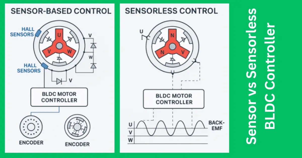
| Feature | Sensor-Based BLDC | Sensorless BLDC |
| Rotor Detection | Hall sensors or encoders | Back-EMF estimation |
| Startup | Excellent performance | Needs algorithm to detect position |
| Cost | Higher due to sensors | Lower, simpler design |
| Reliability | Sensitive to environment | High, fewer components |
| Applications | EVs, robotics, automation | Fans, pumps, drones |
Selecting between the two depends on cost, accuracy, and operating environment.
Modern DSP Algorithms in BLDC Controllers
Today’s controllers use Digital Signal Processors (DSPs) or microcontrollers (like STM32, TI, or Infineon) to execute intelligent algorithms for precise control.
Common Techniques:
- Field-Oriented Control (FOC): Ensures sinusoidal commutation and smooth torque.
- Extended Kalman Filters (EKF): Estimate position and speed under noise.
- Sliding Mode Observers: Improve robustness under varying load and temperature.
These algorithms help achieve high efficiency, low noise, and superior dynamic response, vital in EVs and robotics.
Importance of PCB Design in BLDC Controllers
A well-engineered PCB (Printed Circuit Board) is critical to controller performance.
Key Design Factors:
- Thermal Management: Use copper pours, thermal vias, and heat sinks.
- Signal Integrity: Ground planes and proper shielding reduce EMI.
- Current Handling: Wider copper traces manage high currents.
- Compactness: Multi-layer PCBs integrate logic and power stages efficiently.
A poor PCB layout can cause electromagnetic interference, overheating, or switching failures, reducing motor efficiency.
Power Electronics in BLDC Controllers
The controller’s power stage converts DC supply into 3-phase AC signals using switching devices:
- MOSFETs: For low-voltage, high-speed applications (drones, appliances).
- IGBTs: For high-voltage, high-current systems (EVs, industrial drives).
- Gate Drivers: Ensure fast switching and protect transistors from short circuits.
Proper device selection, gate control, and heat management directly influence system performance and durability.
Communication Interfaces in Modern BLDC Controllers
Advanced controllers often support communication protocols for monitoring and diagnostics:
- CAN bus: Used in automotive and EV systems.
- RS-485 / Modbus: For factory automation.
- I²C / SPI / UART: For embedded and IoT applications.
These interfaces allow integration into smart control networks for predictive maintenance and real-time feedback.
Thermal Management and Protection Systems
Temperature control is vital for long-term reliability. Typical solutions include:
- Copper planes and aluminum substrates for heat dissipation.
- NTC sensors or thermistors for thermal feedback.
- Active cooling systems (liquid or forced air) in EVs.
- Dynamic power throttling based on temperature readings.
Smart thermal management ensures stable operation even under continuous heavy load.
Applications of BLDC Controllers Across Industries
| Industry | Application | Control Type |
| Electric Vehicles | Traction, regenerative braking | Sensor-based / FOC |
| Drones & UAVs | Propulsion motors | Sensorless |
| Robotics | Servo joints, actuators | Encoder-based |
| Medical Devices | Pumps, surgical robots | High-resolution encoders |
| HVAC & Appliances | Fans, compressors | Sensorless |
The choice of control method depends on precision, torque demand, cost, and size constraints.
Conclusion
A BLDC motor controller is far more than a simple power switch — it is a smart, adaptive system that converts DC input into precisely timed phase voltages, ensuring efficient and smooth motor operation.
To truly understand how a BLDC motor controller works, it’s important to look at how it blends power electronics, sensors, DSP algorithms, and optimized PCB design to achieve high performance. Modern controllers deliver unmatched efficiency, torque control, and reliability across industries ranging from drones to electric vehicles.
As BLDC motor control technology continues to evolve, future controllers will feature AI-assisted tuning, edge computing, and ultra-compact architectures, making them the backbone of next-generation motion systems and a key focus in understanding how a BLDC motor controller works in real-world applications.
Related Articles: