This article explains the Hall Effect sensor working principle and its important applications in modern electronics. The Hall Effect, discovered by Edwin H. Hall in 1879, is a fundamental electromagnetic phenomenon in which a voltage is generated across a current-carrying conductor when it is placed in a magnetic field.
Based on this principle, Hall Effect sensors are used to detect magnetic fields and identify whether charge carriers are positively or negatively charged. Due to their accuracy, reliability, and non-contact operation, Hall Effect sensors are widely used in automotive systems, industrial automation, position sensing, speed detection, and current measurement applications.
Theory of Hall Effect Sensor
The magnetic force acting on a moving charge is given by F = q (v × B). When the system reaches equilibrium, the magnetic force is balanced by the opposing electric force, resulting in a net force of zero on the charge carriers.
Therefore,
Therefore,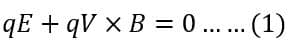
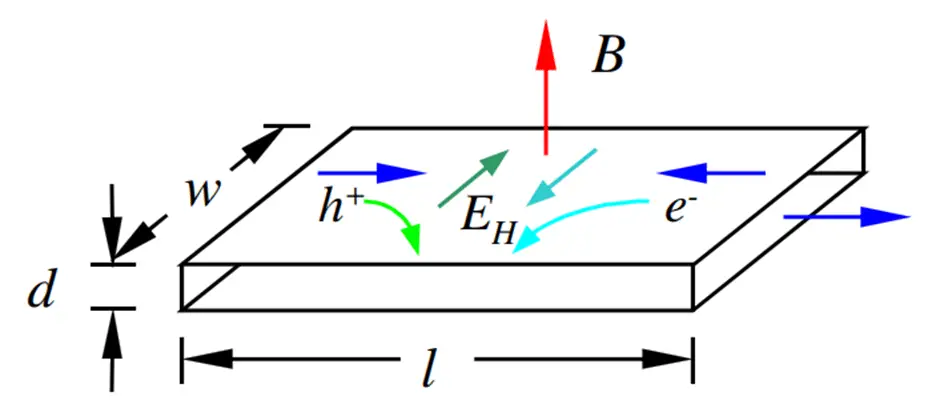
Figure 1: A conducting strip of length l, width w, and diameter d immersed in a magnetic field B
Consider a conductor with length L, thickness t, and width w, as shown in Figure 1. The charge carriers within the conductor have a charge q, number density n, and drift velocity vₓ. In this configuration, the electric field (E) and the magnetic field (B) are mutually perpendicular, as illustrated in Figure 1.
so,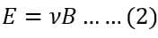
The current flowing through the conductor can be expressed as
Simplifying Eq(2) and Eq(3), we get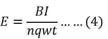
The transverse potential difference generated across the conductor is expressed as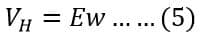
Eq(5) can be rewritten as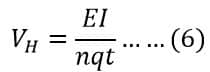
Eq(6) clearly indicates the relationship of Hall voltage with carrier mobility, conductivity, and carrier concentration. Therefore, the selection of semiconductor material plays an important role in the design of Hall Effect sensors. Different alloy materials such as InSb, InAs, GaAs, and doped Si are used to construct Hall Effect sensors.
The overall sensitivity of the Hall Effect sensor is defined as Hall Coefficient which can be defined as the electric potential gradient per unit magnetic field intensity per unit current density.
Working Principle of Hall Effect Sensor
The Hall Effect sensor working principle is based on the generation of Hall voltage. When an electric current flows through a thin conducting strip, the electrons move in a straight path. However, upon the application of a magnetic field, the charge carriers experience a force that causes them to deflect in a direction perpendicular to their motion, resulting in the development of a transverse voltage across the conductor.
As electrons accumulate on one side of the conductor and are depleted from the opposite side, one plane of the conductor becomes negatively charged while the other becomes positively charged. This charge separation creates a potential difference across the conductor, and the resulting voltage is known as the Hall voltage.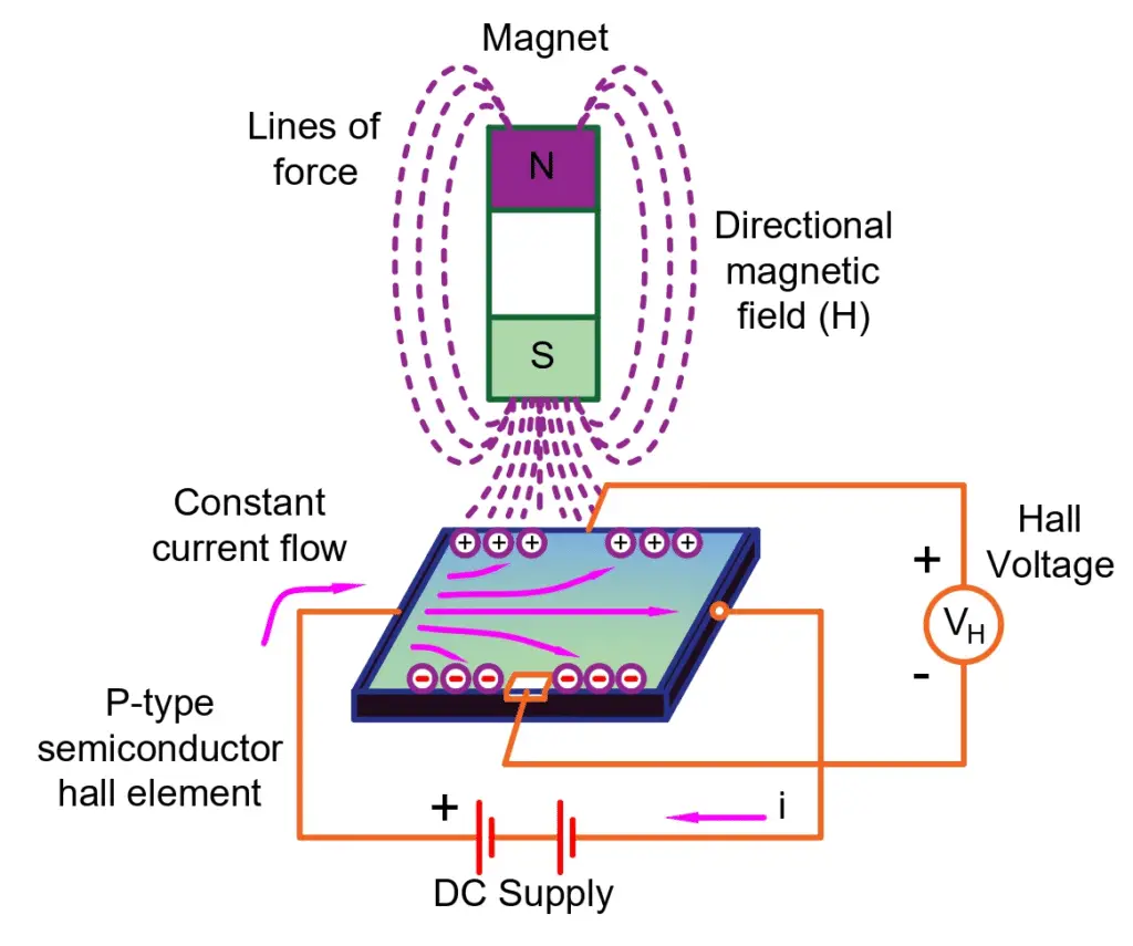
The electrons continue to move from one side of the conductor to the other until an equilibrium condition is reached. This equilibrium occurs when the electric force acting on the charge carriers equals the magnetic force. At this point, the net force on the charged particles becomes zero. Under this condition, the Hall voltage developed across the conductor serves as a direct measure of the magnetic flux density.
Hall Effect sensors can be classified into two types—linear sensors and threshold sensors—based on the relationship between Hall voltage and magnetic flux density. In a linear Hall Effect sensor, the output voltage increases linearly with an increase in magnetic flux density. In contrast, a threshold Hall Effect sensor produces a sharp change in output voltage when the magnetic flux density reaches a specific threshold value.
Design of Measurement System using Hall Effect Sensor
Using the fundamental principle of the Hall Effect, various sensors have been developed for a wide range of applications. A Hall Effect measurement system consists of several key components, such as:
- Hall Effect Sensor
- Signal Conditioning Element
- Signal Processing Element
- Display unit
- Regulated power Supply unit
A Hall Effect sensor is enclosed in a four-terminal package consisting of control terminals and differential output terminals.
Signal Conditioning System for Hall Effect Sensor
A Hall Effect sensor primarily detects the presence of a magnetic field and generates a corresponding output voltage. The magnitude of this voltage depends on the strength of the applied magnetic field. For example, when exposed to a magnetic field of 1 gauss, a Hall Effect sensor produces an analog output voltage of approximately 30 µV.
Since the output voltage of a Hall Effect sensor is very small, proper signal conditioning is required to obtain a usable output. Additionally, the Hall Effect is influenced by ambient temperature, making temperature compensation necessary for accurate operation. Hall Effect sensors are also sensitive to mechanical stress; therefore, they are housed in specially designed packages to minimize stress and ensure reliable performance.
Figure 2 shows the schematic diagram of the analog signal conditioning circuit of the Hall Effect sensor.
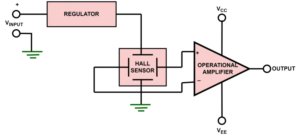
Figure 2: Analog signal conditioning
For signal conditioning, a differential amplifier is employed, which has the following characteristics:
- High input impedance
- Low noise level
- High amplification gain
ome of the important design steps involved in the signal conditioning unit of this sensor are discussed below.
- Since the measured magnetic field can have both positive and negative polarity, the signal conditioning circuit of a Hall Effect sensor must provide both positive and negative output voltages. To eliminate the need for separate power supplies for each polarity, an offset circuit is employed to handle the voltage shift effectively.
- To prevent the output voltage of the Hall Effect sensor from exceeding its limits, saturation levels are imposed for both the positive and negative voltages.
- The Hall Effect output voltage is dependent on the current passing through the sensor. Therefore, a current regulator is used to maintain a stable current and ensure accurate voltage output.
Figure 3 illustrates the signal conditioning system of a Hall Effect sensor with digital output. A key advantage of a digital Hall Effect sensor is that it provides a clear logic output—either logic 1 or logic 0—depending on the presence or absence of a magnetic field. This makes it easy to interface the sensor with microcontrollers, microprocessors, and other digital devices.
To obtain a digital output, the analog output from the differential amplifier is fed into a Schmitt trigger circuit. The Schmitt trigger compares the actual signal with a pre-set threshold and generates a logic 0 or logic 1 accordingly. Since the driving capability of the digital output is limited, the output stage is typically implemented using an open-collector (NPN transistor) or open-drain configuration to interface effectively with external circuits.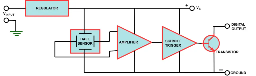
Figure 3: Digital signal conditioning of Hall Effect Sensor
Applications of Hall Effect Sensor
Hall Effect Current Sensor
The Hall Effect is widely used in various sensor design applications. One of the most important designs is the Hall Effect Current Sensor (HECS), which can measure both AC and DC currents—a task classical current transformers cannot perform for DC. HECS finds extensive applications in areas such as industrial AC and DC drives, electric vehicles, power and energy monitoring, power quality analysis, and feedback control in power converters.
The selection of an appropriate Hall Effect Current Sensor (HECS) is a critical design challenge due to several factors, including:
- Current range: Peak current, transient overload current, nominal current
- Required output: Voltage, the scaling factor
- Accuracy: Considering the nonlinearity and DC offset at ambient temperature
- Power Supply: Positive or negative power supply
- Frequency Range: Fundamental operating frequency, Harmonic content
- di/dt and dv/dt rating: Rate of change of current and voltage limit
There are different challenges to designing HECS such as
Here’s a polished rewrite in bullet form while keeping it simple and clear:
- HECS should have a wide dynamic range
- HECS should have a compact size
- HECS should operate at high speed
- HECS should be cost-effective
There are two main types of Hall Effect Current Sensors (HECS): open-loop and closed-loop. Open-loop HECS have several limitations, including larger physical size, magnetic saturation, nonlinearity, and core heating. As a result, closed-loop HECS are more widely used, as illustrated in Figure 4.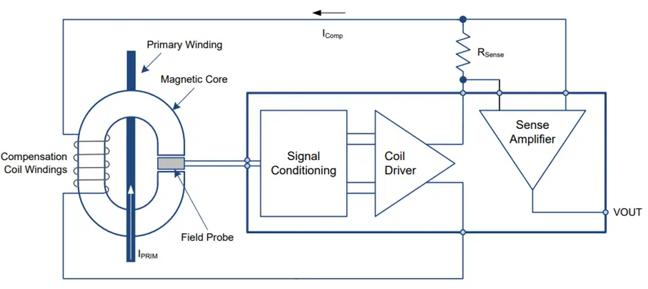
Figure 4: Block diagram of closed-loop Hall Effect Sensor with signal conditioning circuit
Despite its many advantages, closed-loop Hall Effect Current Sensors (HECS) have several limitations, including:
- Gain drift due to changes in temperature
- Magnetic offset
- DC offset
- Nonlinearity
Table 1: Summary of different Hall Effect current sensorsPart Number Bandwidth (MHz) Slope Rise time (nsec) DC Signal measurement Isolation Size Rating ABB EL50P1 0.2 — Yes Yes Medium RMS: 50 A P-P: ±80 A LEM LA-55-P 0.2 500 Yes Yes Medium RMS: 50 A P-P: ±70 A ACS70331 1 — Yes Yes Small 5 A ACS7002MA 0.4 — Yes Yes Small ±100 A
Hall Effect Switch
Hall Effect sensors are also widely used as switches, including proximity switches and reed switches. A Hall Effect switch turns ON or OFF in response to the presence of a magnetic field, making it ideal for proximity detection applications. These switches are commonly employed in industrial automation, robotics, and safety systems. Some examples of industrial Hall Effect switches include:
- TLE496X – Used in automotive applications
- TLI496X – Designed for industrial purposes, such as position detection in BLDC motors
- TLV496X – Suited for consumer applications, including e-bikes and fans
Hall Effect sensors are widely used for measuring the velocity, displacement, and position of rotating shafts. These sensors can be applied in two main types of motor assembly configurations for position and displacement sensing:
- Magnetic rotor assembly: In this configuration, the magnets are mounted on the rotor, while the sensor remains stationary.
- Ferrous vane rotor assembly: In this setup, the magnets are stationary, and the rotor contains ferrous vanes that modulate the magnetic field detected by the sensor.
Conclusion
Hall Effect sensors are smart and reliable devices that detect magnetic fields and turn them into useful signals. They can measure current, position, speed, and movement without touching the object, which makes them widely used in cars, industrial machines, and everyday electronics. With the right setup and care, these sensors provide accurate, efficient, and long-lasting performance in many applications.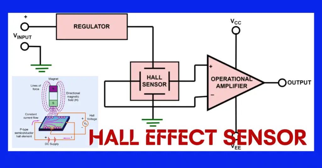
Read Next: