Dynamic Braking in VFD is a technique used to safely stop high-inertia loads by dissipating excess energy through braking resistors. Variable Frequency Drives (VFDs) are widely used to control the speed of induction motors, and dynamic braking plays a key role in their operation.
In this article, we’ll explore how dynamic braking works in VFDs, its components, and its practical applications.
What is Dynamic Braking in VFD?
Dynamic braking is the method of stopping the motor by dissipation of heat in the resistor. When VFD drives a motor, the motor acts as a generator when the motor’s actual speed is more than the VFD frequency. The generated energy dissipates in the resistor( Dynamic braking resistor), leading to the motor’s braking.
This setup forms the core of a dynamic braking system in variable frequency drives, where braking resistors safely handle excess regenerative energy.
Why is Braking Required?
When the motor is required to stop faster than the normal speed of the motor, it is known as the braking of the motor. During the motor’s deceleration, the motor’s actual speed can be more than the drive set point if the load inertia is greater.
The opposite torque against the normal running torque is applied to bring the motor speed down as per the set point of the inverter frequency.
Braking is required in applications like centrifugal fans and rotary kilns because of high inertia loads. The braking is also required in machine tools, winches, and crane applications. In such cases, using a dynamic braking resistor in VFDs ensures reliable and safe stopping without damaging the drive.
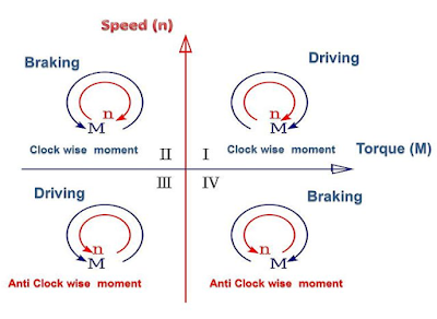
The motor can be operated in four quadrants: Forward and reverse driving and forward & reverse braking.
Types of Braking in VFDs
Because of high inertia, the load connected to the motor shaft does not allow the motor to decrease the speed at the same rate as the inverter frequency.
In this condition, the motor speed is more than the synchronous speed of the motor, and it will work as a generator. The synchronous speed of the motor is;
s= (Ns-N)/Ns
s- slip, Ns- Synchronous speed, N- actual Rotor speed,
If the motor’s actual speed is more than the synchronous speed, the slip of the motor is negative, and the motor will act as a generator.
As a result, the motor starts feeding energy to the source side. The energy can either be dissipated in resistance or fed to the source for braking the motor.
There are three methods that can be used for breaking the motor.
1. DC injection in the stator of the motor
2. Dynamic braking
3. Regenerative braking
DC Braking
DC braking is another method used in VFDs to stop the motor. In this method, DC voltage is injected into the stator windings after the AC voltage is removed. This creates a stationary magnetic field that resists rotor movement, helping to bring the motor to a stop.
While effective for short stops, it’s less suitable for high-inertia loads compared to dynamic braking.
Read detailed article on: DC Injection Braking in VFD
Regenerative Braking
Regenerative braking is a method where the motor feeds excess energy back into the power supply. When the motor slows down, it acts as a generator, converting mechanical energy into electrical energy. Instead of dissipating this energy as heat, the VFD redirects it to the power grid or a common DC bus.
This makes regenerative braking energy-efficient, especially in applications with frequent start-stop cycles. However, it requires more complex and expensive hardware than dynamic braking.
Dynamic Braking – At a Glance
Dynamic braking works by turning extra energy into heat using a resistor when the motor slows down. It is often used in VFDs for stopping heavy loads and doesn’t send energy back to the power supply.
Among these, dynamic braking in VFDs is the most cost-effective solution where regenerative braking is not feasible. It is also easier to implement since it does not require feeding energy back to the grid, unlike regenerative braking.
Let us now discuss dynamic braking in detail, primarily used in variable frequency drives(VFds).
How Dynamic Braking Works in Variable Frequency Drives
Working Principle of VFD
First, let us understand the working principle of the VF drive. The drive has three major sections: the converter, DC capacitor, and inverter.
The converter section rectifies the three-phase supply using the p-n junction diodes or the IGBTs. The converter section can be of 6 pulses or 12-pulse configurations.
If the drive is of large rating, 12 pulse rectifications should be preferred so that lower-order harmonics 5th and 7th eliminates.
The block diagram of the VF drive is given below.
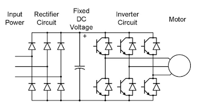
The input three-phase supply is fed to the diode bridge rectifier that converts AC voltage into DC voltage. The magnitude of the DC voltage at the capacitor terminal is 1.35 * Vrms, where Vrms is the input supply’s root mean square (RMS) value.
The DC voltage is fed to the inverter circuit. The inverter circuit has six IGBTs (Insulated Gate Bipolar Transistor). The IGBTs are switched on and off through the PWM(pulse width modulator) controller.
In pulse width modulation, the carrier frequency (Range 1KHz-15 KHz) is modulated with the sinusoidal frequency (Range 0.1 -50 Hz) to get the base drive pulses.
In the PWM inverter, both the voltage and frequency are increased/decreased at the same rate to maintain the constant flux in the motor to ensure constant torque delivery.
Read detailed artcile on: What is a VFD? – Its Working, Applications, Advantages
Working Principle of Dynamic Braking in VFD
When the motor is driving a high inertia load and if the speed of the motor is reduced by decreasing the frequency, the speed of the driving equipment does not lower according to the set point of the inverter.
In this condition, the actual speed of the motor is more than the synchronous speed, and the motor acts as a generator, and it starts feeding energy into the capacitor bank through the IGBTs of the inverter.
As a result of this, the voltage across the capacitor bank increases. This can trigger an overvoltage fault if not controlled by the braking system.
In normal conditions, for a 440 Volt drive, the voltage across the capacitor is 635 volts; however, if the motor goes into generating mode, the voltage across the capacitor bank increases.
The additional energy that gets stored in the capacitor bank during generating mode operation needs to be dissipated to lower the speed of the motor.
This is achieved using a dynamic braking resistor for VFD, which ensures stable system voltage during deceleration.
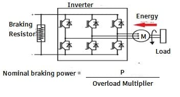
Role of Braking Resistors
In a VFD system, braking resistors are used to absorb extra energy produced when the motor slows down. During deceleration, the motor can act like a generator and send energy back into the system. This energy is sent to the braking resistor, where it is safely converted into heat.
This dynamic braking resistor working principle helps avoid overvoltage problems and allows smooth braking, especially in high-inertia loads.
The resistor value and power rating are chosen based on load inertia and deceleration needs, making it a crucial part of the VFD braking system
Block Diagram of VFD with Dynamic Braking Resistor
The block diagram of the dynamic braking in VFD is given below.
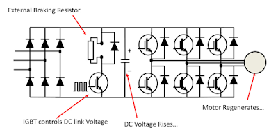
When the voltage increases above its rated voltage, the drive senses it as an over-voltage, and the controller switches on the dynamic braking transistor, and the additional energy gets dissipated in the braking resistor.
The capacitor voltage returns to normal voltage level after dissipating the additional energy in the braking resistor. This method of braking is especially useful in VFD applications like elevators, hoists, and conveyors where rapid and controlled deceleration is essential.
The braking resistor working principle is to convert the electrical energy into thermal energy, preventing overvoltage and enabling efficient braking.
Comparison Table: DC Braking vs Dynamic Braking vs Regenerative Braking
Each braking method in a VFD has its own working principle, cost, and suitability for different applications. The table below compares DC braking, dynamic braking, and regenerative braking to help understand their key differences.
| Feature | DC Braking | Dynamic Braking | Regenerative Braking |
| Working Principle | Injects DC into stator windings | Dissipates excess energy in a resistor | Returns energy to the power supply |
| Efficiency | Low | Moderate | High |
| Energy Usage | Wasted as heat | Wasted as heat in resistor | Reused or fed back to the grid |
| Cost | Low | Medium | High |
| Best For | Short stop, low-inertia loads | High-inertia loads | Energy recovery applications |
Key Takeaways
- Dynamic braking helps quickly stop motors by dissipating energy as heat.
- It uses braking resistors and switching transistors inside the VFD.
- Effective for high-inertia systems like fans, cranes, and elevators.
- Protects the drive by avoiding overvoltage during deceleration.
Conclusion
Dynamic braking is an essential technique used in VFDs to control the deceleration of high-inertia loads safely and effectively. By converting the motor’s regenerative energy into heat through braking resistors, it prevents overvoltage conditions and ensures smoother motor stops.
Compared to DC injection braking and regenerative braking, dynamic braking stands out as a cost-effective and practical solution—especially where quick stopping is critical but energy recovery is not feasible.
Understanding the dynamic braking resistor working principle and how it integrates into the VFD circuit helps in selecting the right braking method for your application.
Whether it’s a crane, conveyor, or fan system, VFD dynamic braking plays a vital role in protecting equipment, improving performance, and enhancing operational safety.
FAQs
Dynamic braking in VFD is a method of slowing down a motor by converting the excess energy generated during deceleration into heat using braking resistors. It’s commonly used for high-inertia loads to prevent overvoltage and ensure controlled stopping.
When the motor slows down and acts as a generator, it sends extra energy back into the system. A braking transistor detects this and directs the energy to the braking resistor, where it is safely dissipated as heat. This prevents voltage buildup in the DC bus.
DC braking injects direct current into the motor windings to create a stationary magnetic field, while dynamic braking uses resistors to dissipate excess energy. DC braking is suitable for short stops, whereas dynamic braking is better for high-inertia applications.
The main disadvantage is energy loss as heat. Also, braking resistors need space, proper cooling, and must be sized correctly to avoid overheating.
No. In dynamic braking, energy is wasted as heat. In regenerative braking, the excess energy is fed back to the power supply or grid, making it more energy-efficient but costlier to implement.
Related Articles:
Good learning platform