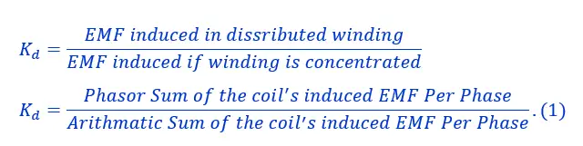
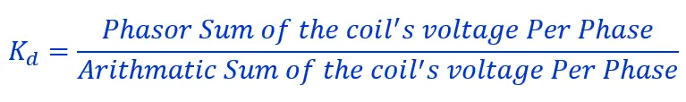
Definition: The Distribution Factor. also known as the Breadth Factor, is the ratio of the actual voltage obtained to the possible voltage if all the coils of a polar group were concentrated in a single slot. This factor is represented by the symbol Kd.
Distribution Factor Formula
The formula of kd is given below.
Derivation of Distribution Factor Formula
As we discussed, the distribution factor is the ratio of the voltage when the coil is concentrated and when it is distributed. Therefore, we will calculate the coil’s voltage in both cases to find kd.
In concentrated winding, each phase of a coil is placed in a single slot. The voltage induced in each coil is in phase with the others. To calculate the total induced voltage per phase, we need to add these individual voltages together arithmetically. This can be done by multiplying the voltage of a given coil by the number of coils that are connected in series per phase. However, in actual practice, coils in each phase are not placed in a single slot. Rather, they are distributed in a number of slots in space to form a polar group under each pole.
The voltage induced in the distributed winding is not in phase and differs by angle β, which is known as the angular displacement of the slots. The phasor sum of the total induced voltage in the coil is equal to the vector sum of the voltage induced in any phase of the coil.
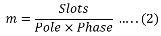
Let there be m slots/pole/phase. Therefore,
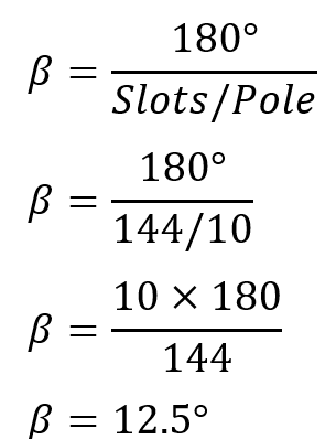
The angular displacement exists when the winding is distributed, which can be mathematically expressed as;
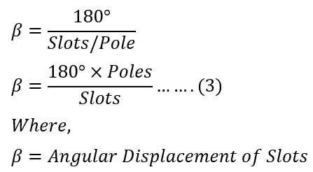
Thus, one phase of the winding consists of coils arranged in m consecutive slots. Voltages EC1, EC2, EC3, EC4….. are the individual coil voltages. Each coil voltage EC will be out of phase with the next coil voltages by the slot pitch β.
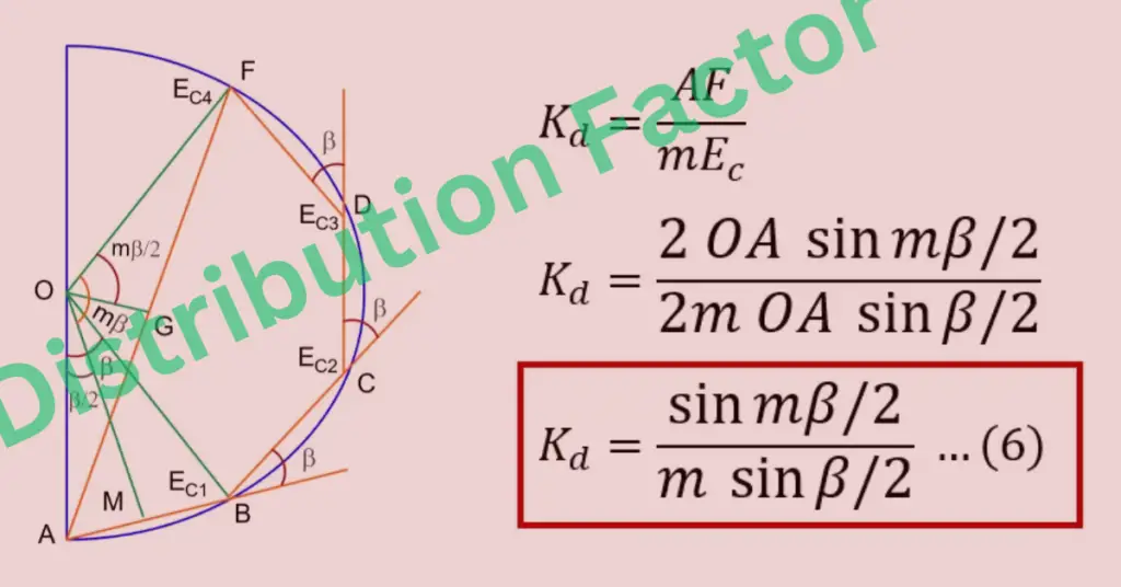
The diagram below presents the induced voltages in the four coils of a group (m = 4).
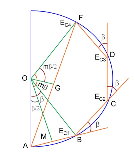
The voltages EC1, EC2, EC3, and EC4 are represented by the phasors AB, BC, CD, and DF, respectively. Each of these phasors is a chord of a circle with the center O and subtends an angle β at the point O. The phasor sum AF, represents the resultant winding voltage, subtends at an angle mβ at the center.
The voltages EC1, EC2, EC3, and EC4 can be shown as phasors AB, BC, CD, and DF, respectively. These phasors are chords of a circle with center O, and they create an angle of β at point O. The total winding voltage is represented by phasor sum AF, which forms an angle of mβ at the center.
You can calculate the sum of voltages induced in the coil using arithmetic and vector methods.
Finding the arithmetic sum of the individual coil voltage
The total coil group= m
The voltage induced in each coil= EC
The aritmatic sum of voltage = m X EC
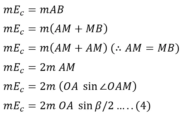
Finding the phasor sum of the individual coil voltage
Phasor sum of coil’s voltage = AF
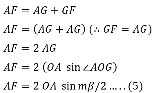
The distribution factor is,
Putting the value of equations 4 and 5 in the above equation,
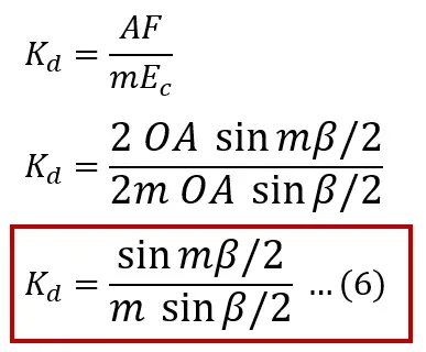
The distribution factor, Kd, is solely dependent on the number of distributed slots under a given pole, irrespective of the winding type (lap or wave) or the number of turns per coil. As the number of slots per pole increases, the distribution factor decreases.
Solved Examples
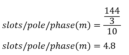
A 10-pole, 11kV, 50Hz low-speed hydro generator with 144 slots has a two-layer diamond winding with five conductors per coil side in each slot. Calculate the distribution factor.
Solution-
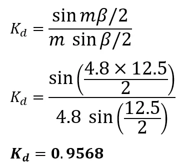
Slots/Pole/Phase is;
Angular displacement is;
The distribution factor Kd is;