The armature of a DC motor is one of its most essential parts. It’s the rotating section that converts electrical energy into mechanical energy through electromagnetic induction. In simple words, the armature is the part that produces the motor’s turning force, known as torque.
What is Armature in DC Motor?
The armature is the component of a DC motor that carries current and interacts with the magnetic field produced by the stator or field winding. This interaction generates a force on the armature conductors, causing the shaft to rotate.
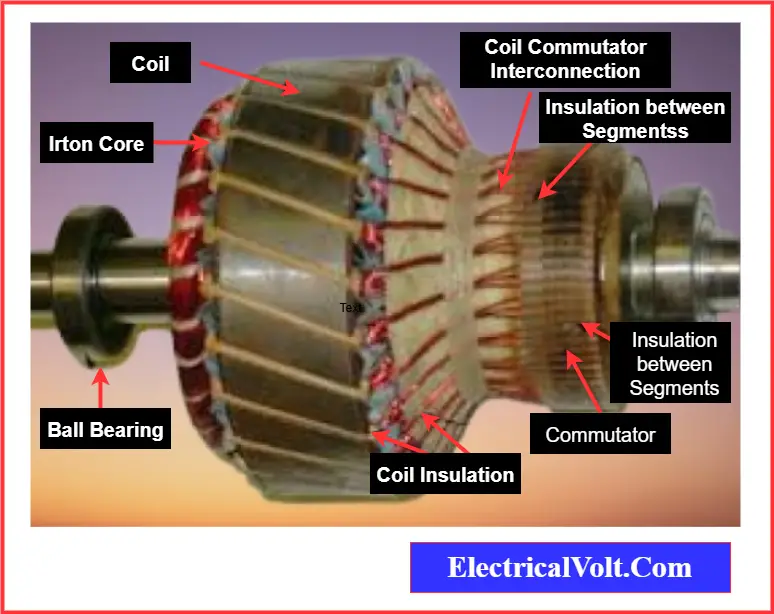
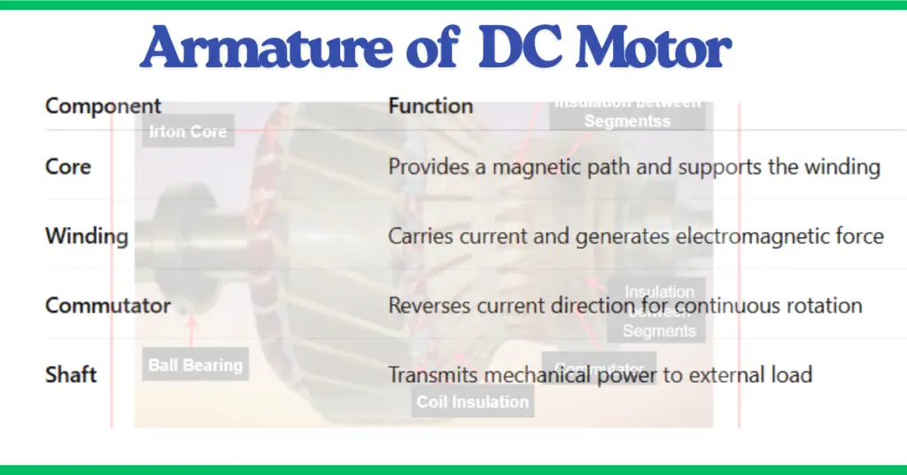
It is made up of several parts — core, winding, commutator, and shaft — all working together to ensure smooth and efficient motion.
Main Components of the Armature & Diagram
1. Armature Core
The armature core is built from thin laminated sheets of silicon steel. These laminations are insulated from each other to reduce eddy current losses and heat buildup.
Its primary purpose is to provide a low-reluctance path for magnetic flux and hold the armature winding securely in place.
2. Armature Winding
The armature winding is made of insulated copper conductors placed in the slots of the armature core. When current flows through these coils, it creates an electromagnetic field that interacts with the main magnetic field of the stator.
This interaction produces torque and causes the armature to rotate. Proper insulation ensures that adjacent coils do not short-circuit and that the winding remains efficient and safe.
Read detailed article: What is Armature Winding? Turn, Coil & Field Winding
3. Commutator
The commutator is a cylindrical copper segment mounted on the motor shaft. It connects the armature winding to the external circuit through carbon brushes.
Its main function is to reverse the direction of current in each coil every half turn. This switching action ensures that the torque remains in the same direction, allowing the motor to rotate continuously and smoothly.
4. Shaft
The shaft is the rotating rod attached to the armature. It transfers the mechanical power generated by the armature to external loads like fans, conveyors, or pumps. The shaft must be precisely balanced and strong enough to handle mechanical stress.
Working Principle of Armature of DC Motor
The armature of a DC motor works on the principle that when a current-carrying conductor is placed in a magnetic field, it experiences a mechanical force. This fundamental concept is derived from Lorentz’s force law and is often demonstrated using Fleming’s left-hand rule.
When a DC supply is applied to the motor, current flows through the armature winding. This current creates its own magnetic field, which interacts with the magnetic field produced by the stator poles. The interaction of these two magnetic fields generates a force on the armature conductors.
These forces combine to produce a torque that acts on the armature, causing it to rotate. As the armature turns, the commutator plays a crucial role—it continuously reverses the direction of current in each coil at the proper moment. This ensures that the torque always acts in the same rotational direction, providing smooth and continuous motion.
The rotating armature shaft then delivers this mechanical energy to external devices, effectively converting the electrical energy supplied to the motor into useful mechanical energy for driving loads such as fans, pumps, or conveyors.
Losses in Armature of DC Motor
The armature in an electric machine experiences several types of losses that reduce its overall efficiency and performance. These losses primarily include copper loss, eddy current loss, and hysteresis loss.
1. Copper Loss
Copper loss occurs because of the electrical resistance in the armature winding. When current flows through the winding, part of the electrical energy is converted into heat, which results in power loss. This loss increases with the square of the armature current.
It can be reduced by using thicker copper wires, providing multiple parallel paths for current, or improving the winding design to lower resistance.
2. Eddy Current Loss
Eddy current loss is caused by circulating currents that are induced within the armature core due to alternating magnetic flux. These unwanted currents generate heat and waste energy, lowering machine efficiency.
To minimize this loss, the armature core is built from thin laminated sheets insulated from each other, which restricts the flow of eddy currents and reduces heating.
3. Hysteresis Loss
Hysteresis loss happens when the magnetic material of the armature core is repeatedly magnetized and demagnetized as the magnetic field changes direction. This constant magnetic reversal causes internal friction and heat within the core material.
The loss can be minimized by using soft magnetic materials like silicon steel, which have low coercivity and high permeability, allowing easy magnetization and demagnetization.
Total Armature Loss
The total armature loss is the sum of all three losses — copper loss, eddy current loss, and hysteresis loss. Together, they determine how much electrical energy is lost as heat instead of being converted into mechanical output.
Armature Efficiency
Armature efficiency is the ratio of the output power to the input power. A higher efficiency means the armature converts most of the input electrical energy into useful mechanical energy, with minimal losses. Good design practices, high-quality materials, and proper cooling help improve armature efficiency.
Efficiency and Design Considerations
The performance and efficiency of a DC motor depend heavily on the design of its armature.
Key design aspects include:
- Lamination thickness: Thinner laminations reduce eddy current losses.
- Winding type: Lap and wave windings affect current capacity and torque output.
- Insulation quality: Prevents short circuits and enhances durability.
- Material choice: Using high-grade silicon steel improves magnetic efficiency.
A well-designed armature minimizes energy loss, improves torque, and extends motor life.
Maintenance of Armature
Regular maintenance is important to keep the armature of a DC motor in good working condition:
- Check for brush wear: Worn brushes can cause sparking and poor commutation.
- Clean the commutator surface: Dirt or carbon deposits can reduce efficiency.
- Inspect winding insulation: Cracks or burns may lead to short circuits.
- Lubricate bearings: Prevent friction and ensure smooth shaft rotation.
Proper maintenance enhances performance and prevents costly breakdowns.
Applications of DC Motor Armatures
Armatures are used in various types of DC motors, including shunt, series, and compound motors. These motors are found in:
- Electric vehicles
- Power tools
- Elevators and cranes
- Conveyor systems
- Industrial machinery
The reliability and efficiency of these devices largely depend on the armature’s performance.
Conclusion
The armature of a DC motor plays a vital role in converting electrical energy into mechanical motion. Its coordinated components — core, winding, commutator, and shaft — work together to generate torque and ensure smooth operation.
A clear understanding of its structure, working principle, and maintenance is essential for designing and maintaining efficient DC motors.
Related Article: