A ceramic capacitor has ceramic material as its dielectric. These capacitors are of three types- multilayer, ceramic disc, and ceramic chip capacitors.
Capacitors are tiny in physical structure but they play a crucial role in today’s electronics. Ceramic capacitors are one of them. They were developed in Germany to replace mica as a dielectric in a capacitor. They are widely used in different applications such as computers and mobile phones to store and release charge. In this article, we will study the ceramic capacitor in detail. Let’s start our topic!
Definition of Ceramic Capacitor
There are lots of capacitors in electronics with both variable and fixed types of capacitance in their operation. Ceramic capacitors are of fixed capacitance type. We can define a ceramic capacitor as a “capacitor with a fixed value of capacitance with a ceramic material as is dielectric used to store and release the electric charge”.
The dielectric material in a capacitor determines its capacitance. The dielectric material in ceramic capacitors comprises ceramic material (non-metal and inorganic material) like barium titanate or other metal oxides (Titanium Dioxide).
These capacitors are non-polarized in nature. This property indicates that they do not carry a positive or negative terminal. Its capacitance is measured in a specific unit called Farads (F). Sometimes it is divided into sub-units like picofarads (mF) or microfarads (µF).
Symbol of Ceramic Capacitor
These capacitors do not have polarity as mentioned above due to their non-polarized nature. The symbol of the ceramic capacitor is given below.
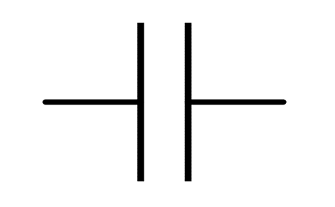
You can connect the capacitor in any direction as it does not contain any polarity (positive & negative symbols).
Construction of Ceramic Capacitor
A ceramic capacitor has a dielectric material made up of barium titanate, titanium dioxide, or other metal oxides. This dielectric plays the role of the heart in a capacitor. These capacitors have two conductive terminals called electrodes in their construction. These electrodes are placed on the opposite side of the capacitor.
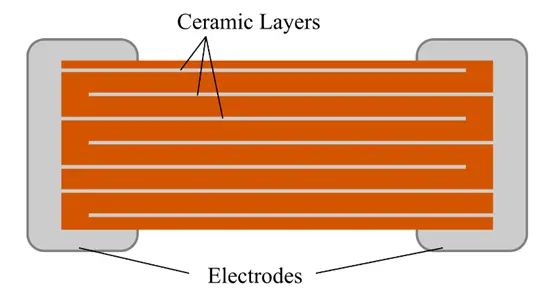
These electrodes are made of a conductive material, often a metal like silver or palladium, and are coated onto the ceramic material to form a thin conductive layer. These electrodes extend to the edge of the dielectric material and work like the terminal of the capacitor. We use these terminals to add a connection with an external circuit.
In the case of multi-layer ceramic capacitors (MLCCs), we added several layers of ceramic with electrodes on each other to get higher capacitance. This construction helps in different separate capacitors in parallel and also it contributes to the overall capacitance value. Then we provide heat to ceramic and metal to join them together for the final assembly in a small case. This is all about its construction.
Construction may vary on specific type and design requirements but the ceramic material as dielectric and metal as electrodes will remain the same.
How Ceramic Capacitors Work
A ceramic capacitor works by storing electrical energy in an electric field created between two conductive electrodes separated by a ceramic dielectric material. The ceramic dielectric has a high insulating property, allowing the capacitor to store charge efficiently while preventing current from flowing directly between the electrodes.
Charging and Discharging of a Ceramic Capacitor
When a ceramic capacitor is connected to a voltage source, it begins to charge. Electrons accumulate on one electrode, creating a negative charge, while an equal deficiency of electrons develops on the opposite electrode, creating a positive charge. This separation of charges generates an electric field across the ceramic dielectric, and electrical energy is stored within this field.
As the capacitor continues charging, the voltage across its terminals gradually increases until it reaches the same voltage as the power source. At this point, charging stops because the capacitor is fully charged.
When the power source is removed or the capacitor is connected to a load, the stored energy is released. The accumulated charge flows through the circuit from one electrode to the other, supplying current to connected components. This process, known as discharging, continues until the stored energy is depleted and the capacitor voltage falls to zero.
Relationship Between Capacitance and Voltage
The amount of charge a ceramic capacitor can store depends on its capacitance value and the applied voltage. A higher capacitance allows the capacitor to store more electrical charge, making it suitable for applications such as filtering, coupling, decoupling, and energy storage. The rapid charging and discharging capability of ceramic capacitors makes them particularly useful in high-frequency electronic circuits, power supplies, and digital devices.
In simple terms, a ceramic capacitor functions as a temporary energy storage device, repeatedly charging and discharging to stabilize voltage, filter electrical noise, and support the smooth operation of electronic circuits.
Types of Ceramic Capacitors
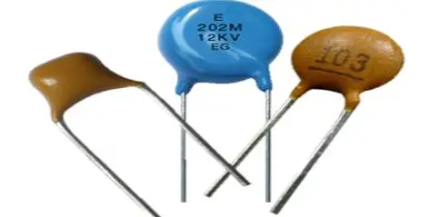
There are different types the ceramic capacitors:
Multi-Layer Ceramic Capacitors (MLCCs)
This is the most common type of ceramic capacitor. It contains multiple layers of ceramic with metal electrodes on each other. This type offers a wide range of capacitances and voltage ratings.
Ceramic Disc Capacitors
This type has a disc-shaped ceramic dielectric with metal electrodes on both sides. They are often used in high-voltage applications and can handle significant transient voltages. They are usually found in power supplies, lighting circuits, and other high-voltage electronic systems. They have capacitance values in the range of 10pF to 100μF.
Ceramic Chip Capacitors
These ceramic chip capacitors are widely used in consumer electronics, communication devices, and also in different digital applications.
Feed-Through Ceramic Capacitors
Feed-through ceramic capacitors are specialized three-terminal capacitors designed to suppress electromagnetic interference (EMI) and radio-frequency interference (RFI). They filter unwanted noise passing through panels, enclosures, bulkheads, or cable entry points while allowing the desired signal or power to pass. These capacitors provide superior high-frequency noise attenuation compared to conventional capacitors and are commonly used in telecommunications equipment, military electronics, medical devices, and industrial control systems.
Power Ceramic Capacitors
Power ceramic capacitors are physically larger capacitors designed to operate under high-voltage, high-frequency, or high-reactive-power conditions. They are built to withstand substantial electrical stress while maintaining reliable performance and low losses. These capacitors are commonly used where high power handling and excellent frequency characteristics are required.
Multi-Layer Ceramic Capacitors (MLCCs) and Ceramic Disc Capacitors are the two most widely used general-purpose ceramic capacitor types. MLCCs are used in modern electronic equipment because their multilayer construction provides high capacitance values in extremely small surface-mount packages. In contrast, ceramic disc capacitors remain a preferred choice for through-hole designs, high-voltage circuits, and applications requiring greater surge voltage handling capability.
Types of Dielectric Classes of Ceramic Capacitor
Ceramic capacitors are categorized into multiple dielectric classes based on the type of dielectric material used. Here are the following classes:
- Class 1: This class is called the high stability and accuracy class due to its very linear temperature coefficient of capacitance, close to zero. Their capacitance value remains almost constant used for different applications such as filters and oscillators. Magnesium titanate dielectric is used for a positive temperature coefficient. Similarly, for a negative temperature coefficient, calcium titanate dielectric is used.
- Class 2: This class offers better results with higher performance and efficiency than class-1. But they also exhibit lower accuracy and are used in those applications where accuracy is not a major concern such as coupling circuits. However, Class 2 capacitors have larger temperature coefficients of capacitance. It indicates that capacitance can change over varying temperatures.
- Class 3: Class 3 capacitors are similar to Class 2 but with a lower dissipation factor. Class 3 is more suitable for applications where tight tolerance or stability is not critical, and cost and higher capacitance are the main concerns. Its temperature may vary from +10oC to +55oC with a dissipation factor of 3 to 5%.
- Class 4: They are also known as Ultra-Stable or U2J capacitors, and they offer an extremely stable temperature coefficient of capacitance. They are suitable for high-performance applications
Standard Ceramic Capacitor Values
Ceramic capacitors are manufactured in standardized capacitance values based on preferred number series, making component selection and replacement easier.
Common Value Series:
- E6 Series: 10, 15, 22, 33, 47, 68
- E12 Series: 10, 12, 15, 18, 22, 27, 33, 39, 47, 56, 68, 82
- E24 Series: Provides additional intermediate values for higher design precision.
Common Ceramic Capacitor Values:
10 pF, 22 pF, 47 pF, 100 pF, 220 pF, 470 pF, 1 nF, 10 nF, 100 nF (0.1 µF), 1 µF, and 10 µF.
These standardized series ensure wide availability and help designers select capacitor values that meet circuit requirements while matching standard tolerance ranges.
Advantages
The advantages are listed below.
- Because they are non-polarized in nature s they are suitable for AC circuits.
- They have higher volumetric efficiency due to their compact size.
- They are available in a wide range of capacitances with a wide range of voltage ratings (they can bear up to 100V).
- They also have lower Equivalent Series Resistance (ESR) and Equivalent Series Inductance (ESL). So they can be used for switching circuits.
- This type of capacitor is cost-effective.
Limitations
These are some limitations of ceramic capacitors:
- They offer less capacitance value to a few microfarads.
- The dielectric in them can be damaged over high voltages.
- They may have voltage-dependent capacitance changes.
- Due to the construction using a ceramic material, there is a risk of cracking or damage in case of mechanical loss.
- Class 2 capacitors may change their capacitance value when they are subject to DC voltage. So this can reduce effective capacitance in an electric circuit.
Applications of Ceramic Capacitors
The different applications are listed below.
- They are used in decoupling to filter out noise and bypass capacitors. They provide stable and smooth power to electronic components.
- They are also used in transmitter stations due to high-power applications in such circuits.
- For general purposes, they can be used due to their non-polarized behavior.
- They are used in converters such as DC to DC.
- They are widely used in radio frequency (RF) circuits such as antennas and filters.
- They are used in flash circuits to store electric energy. They also perform the same function in flash cameras.
Conclusion
Ceramic capacitors are non-polarized and of fixed capacitance type with metal electrodes. These capacitors have ceramic material dielectric. They have different types and can be used depending on different applications. They are cheaper than other types of capacitors but also have their own limitations.
Read Next:
- Different Types of Capacitors & their Applications
- Basics of Resistance Temperature Detector(RTD)
- Wire-Wound Vs Thin-Film Resistance Temperature Detector
- Classification of Engineering Materials
- Can a Capacitor act as a Battery?
- Ultracapacitors and the Ultracapacitor Battery
- Dielectric Material in Capacitors: Definition, Working Principle, Types, and Importance