In this article, we will discuss the instructions for the One Shot Rising and One Shot Falling function in Allen Bradley PLC.
One Shot Rising (OSR)
One shot Rising abbreviated as OSR instruction allows energizing output for a single scan when PLC detects a transition from a logic Low to logic High. The programmer can capture the transition based on One shot Rising instructions. You can find the instruction on the right side of a ladder logic rung. It needs two bits for its operation. The one bit is called the “Storage Bit” and the other is the “Output Bit”. The Output bit can be used to energize other instructions.
One Shot Falling (OSF)
One shot falling abbreviated as OSF instruction allows energizing output for a single scan when PLC detects a transition from a logic High to logic Low. The programmer can capture the transition based on One Shot falling instructions. You can find the instruction on the right side of a ladder logic rung. There are two bits tied to this instruction. The one bit is called the “Storage Bit” and the other is the “Output Bit”. The Output bit can be used to energize other instructions.
PLC Instructions for One Shot Rising and One Shot Falling
The following picture shows the instruction blocks OSR and OSF.
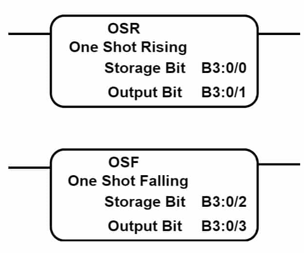
The OSR and OSH have two bits for their operation.
- Storage Bit: This bit stores the input status
- Output Bit: This bit store the value after executing the instructions
PLC Program using OSR and OSF
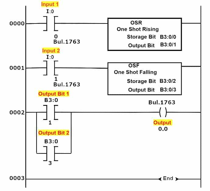
Ladder Logic Explanation
RUNG 0000
- Input 1 (I:0/0) is fed to the OSR block.
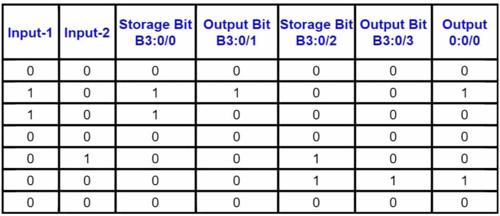
- When Input 1 (I:0/0) is turned on. the storage bit (B3:0/0) changes its state from Low(0) to High(1). The output bit (B3:0/1) changes its state from Low to High for a second and again returns to its initial stage i.e. 0(Low).
RUNG 0001
- Input 2 (I:0/1) is fed to the OSF block.
- When the Input 2 (I:0/1) is turned on-
- Storage bit (B3:0/2) turns “1” and output bit remains “0”
- When the Input 2 (I:0/1) is turned off-
- Output bit (B3:0/3) turns “1” for a second and goes to “0”
- Storage bit(B3:0/2) goes to “0”
Need more information