In this article, we will discuss the Installation precautions of RTD and Thermocouples. These two sensors are widely used for temperature measurement. An improper mounting may lead to erroneous reading, therefore it is very important to mount RTDs and Thermocouples in a proper way.
Depending on the selected process connection, temperature probes such as RTD or thermocouple can be installed in four positions in pipelines or storage tanks.
Regarding orientation, there are no restrictions. It is necessary to ensure the self-drainage of the process. There must be the lowest possible opening in the process connection if faults are to be detected.
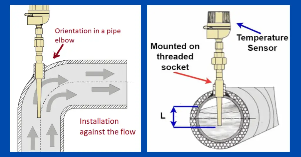
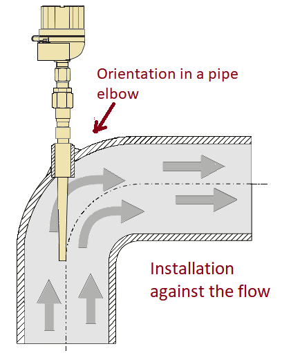
The installation locations should be in such a way that does not have any strong electric field or strong magnetic field. The thermocouple or RTD must be installed against the direction of the flow, as shown in the below figure. In the case of thermocouples, the correct use of compensating cables is very much important.
The temperature sensors, RTD & Thermocouple, can be mounted in the following orientations.
1 General Orientation
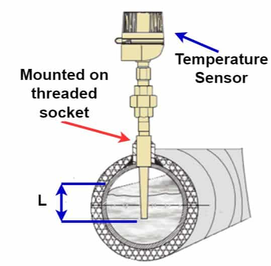
In a pipe with a reduced cross-section, the tip of the sensor must reach or even exceed the central axis of the pipe as shown in the figure below.
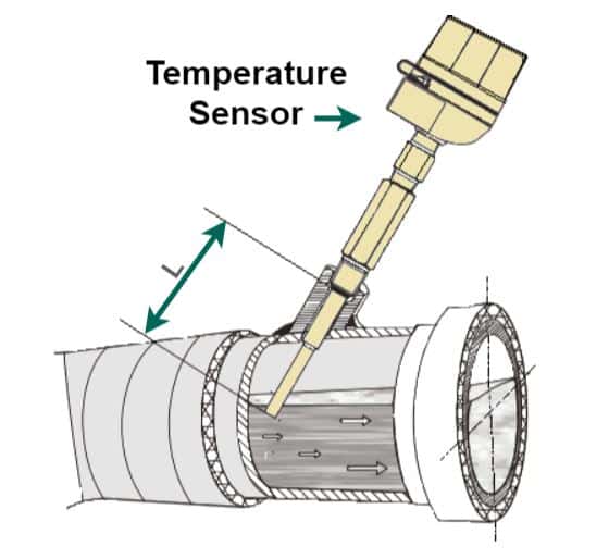
2. Tilted orientation
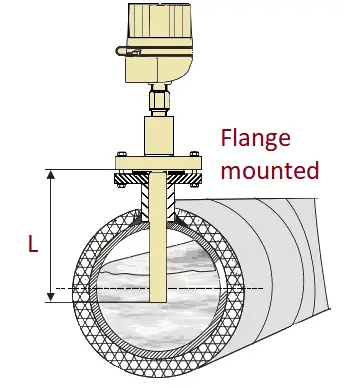
3. Direct orientation
4. Orientation in a pipe elbow.
Key Installation Precautions of RTD & Thermocouple
Measurement accuracy can be affected by the immersion length of the temperature probe.
When the immersion length is too small, measurement errors will be due to heat conduction through the process connection and wall of the container. When installed in a pipe, the immersion length should ideally correspond to half of the pipe diameter. A temperature probe can also be installed at an angle.
In order to determine the immersion length, all the temperature probe and process parameters such as flow rate, and process pressure are to be determined.
- Installation possibilities: Pipes, tanks, or other components of a plant.
- It is important to pay attention to the minimum recommended immersion length.
- The immersion length must be at least eight times the diameter of the Thermowell. Example: Thermowell diameter 10 mm (0.5 Inch) x 8 = 100 mm (3.937).
Installing the temperature probe (RTD or Thermocouple)
- Before installation, it is necessary to check that the equipment does not appear any damage that could be may have produced during delivery from the factory.
- If visible damage is observed, it must be reported immediately. It would be necessary to take into account if it is possible to install the temperature into the process directly or if necessary, use a Thermowell.
For installation, proceed as follows
The allowable load capacity for process connections can be found in the corresponding standards.
- The process connection and compression fitting must comply with the specified maximum process pressures.
- Before applying process pressure, make sure the equipment is installed and secure.
- Adjust the load capacity of the thermowell according to the process conditions.
- For cylindrical threads, it is necessary to use gaskets,
Tapered threads
It is necessary to check and add additional sealing, for example with tape, PTFE, hemp, or welding seams in the case of using NPT threads or other types of threads.
Conical flange
When using flanged connections, the flange of the thermowell must correspond to the part contrary to the part of the process. The gasket used must be suitable for the process and flange geometry. For installation, it is necessary to apply the appropriate torques.
Welded Thermowell
Welded thermowell can be welded directly into the pipe or tank wall, or they can be fixed with a welding fitting. It is necessary to respect the specifications that contain technical data sheets on the materials and applicable guidelines and standards corresponding to the procedure of welding, heat treatment, filler of welding, etc.
Installation instructions of RTD & Thermocouple
In the case of the use of ceramic Thermowell, it is necessary to protect the ceramic Thermowell against mechanical loads.
When installed in a horizontal position, it is necessary to avoid mechanical impacts or bending loads caused by the counterweight of the Thermowell itself.
Depending on the type of material, diameter, length, and design, it is necessary to provide additional support when installed horizontally.
In theory, metal thermowell also experiences the same problems with bending loads. In general, a vertical installation is preferable.
Assurance of Protection after Installation of RTD & Thermocouple
- The head gaskets must be clean and in good condition when inserted into the corresponding slots. The joints will be dried, cleaned, or replaced with new ones whenever necessary.
- All case screws and screw caps must be securely tightened.
- The cables used for the connection must be of the specified external radius (for example M20 x 1.5 cable diameter 8…12 mm).
- Tighten the cable gland securely and use only in the specified tightening area (ensure that the cable diameter is suitable for the cable gland).
- The cables must form a downward loop before passing through the cable gland (“trap anti-water”). This prevents the entry of moisture through the stuffing box. It is necessary to install the equipment so that the fronts of the cable glands are not upward-oriented.
- Do not twist cables and use only round cables.
- Replace unused cable glands with temporary blind connectors.
- Do not remove the grommet from the gland.