EMF Equation of DC Generator and DC Motor
When we apply DC voltage to an armature of a DC motor, a back emf or counter emf generates. The polarity of the back emf is just opposite to the applied DC voltage. Therefore, the back EMF opposes the applied armature voltage. The back EMF limits the armature current in the DC motor. In the case of the generator, when we rotate the generator shaft under the presence of the magnetic field, the emf generates in the armature of dc generator. The generated voltage is called the generated emf or armature voltage. Derivation of EMF equation of Generator and DC motor and shall be discussed in the subsequent section of this article.
The principle of operation of both DC motor and DC generator is the same and the cause of the EMF generated in both the machines is the same- rotation and magnetic field. Therefore, the expression for both the operation – DC generation & DC motoring – is the same. The same formula is applicable for emf generation of DC generator and DC motor. We denote back EMF of DC motor by Eb and armature EMF of DC generator by Eg.
Derivation of EMF Equation of a DC Generator and DC Motor
Let,
- P – Number of Poles in the machine
- ϕ – Flux per pole in Weber.
- Z – Total number of armature conductors = Number of slots x Number of Conductors/slot
- N – Armature rotation in revolution per minute (r.p.m).
- A – number of parallel paths in the armature winding.
- Eg – EMF induced in any parallel path in the armature
Derivation for Induced EMF of One Armature Conductor of DC Machine
Let us find the generated EMF in any one of the parallel paths.
Total flux in the machine = Number of poles x Flux/Pole
= P x ϕ = Pϕ Weber ————(1)
For N revolution it takes – 1 Minute = 60 Seconds
Therefore, it takes 1 revolution in = 60/ N Seconds
Time taken to complete one revolution = 60/ N Seconds ——(2)
According to Faraday’s Second Law of Electromagnetic Induction, the induced emf in a coil is equal to the rate of change of flux linkage to the coil.
Average EMF generated/ Conductor
= dϕ/dt
= Total Flux/Time taken in one revolution
= Pϕ / (60/N)
= ϕPN/60 ————(3)
| Average EMF generated/ Conductor = ϕPN/60 ——(4) |
The generator armature winding is of two types.
- Simplex wave- wound
- Simplex lap- wound
For a simplex wave-wound generator
Number of parallel Path = 2
Number of conductor (in series) with one path =Z/2
EMF generated/ Path = ϕPN/60 x Z/2 = ϕZPN/120
| Average EMF generated/ Conductor(For Simplex Wave wound) = ϕZPN/120 –(5) |
For a simplex wave-wound generator
Number of parallel Path = P
Number of conductors (in series) with one path =Z/P
EMF generated/ Path = ϕPN/60 x Z/P = ϕZN/60
| Average EMF generated/ Conductor(For Simplex Lap wound) = ϕZN/60 –(6) |
In general, Derivation of EMF Equation of DC Generator and DC Motor
Eg= EMF generated in one parallel path x Number of parallel Path —(7)
EMF generated in one parallel path = ϕPN/60 ( from Equation-4) —-(8)
Number of parallel path = Z/ A ——————–(9)
Putting Values of equations (8) and (9) in equation (7), we get
Eg= ϕPN/60 x Z/ A
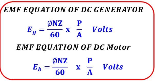
Eg = ϕZN /60 x P/A Volts ————————(10)
| EMF Equation of DC Generator, Eg = ϕZN /60 x P/A Volts |
The same EMF equation is applicable for DC motors. The EMF depends on the speed and the flux. The Generated EMF change with the change in the speed of change in the flux.
| EMF Equation of DC Motor, Eb = ϕZN /60 x P/A Volts |
Eb is the back EMF induced in the armature of the motor.
Solved Problems on EMF equation of DC Generator and DC Motor
Problem-1
A four-pole generator, having wave-wound armature winding has 61 slots, each slot containing 30 conductors. What will be the voltage generated in the machine when driven at 1500 rpm assuming the flux per pole to be 8.0 mWb ?
Eg = ϕZN /60 x P/A Volts
ϕ = 8 X 10⁻³ weberZ =61 x 30= 1830, A = P = 4, ( For wave wound generator A=2)
N = 1500 r.p.m.
Eg = ϕZN /60 x P/A
= (8 X 10-3 X 1830 X 1500) X 4/2
= (8 X 10-3 X 1830 X 1500)/60 X 2
Eg = 732 Volts
Problem-2
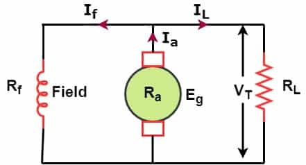
An 8-pole d.c. shunt generator with 798 wave-connected armature conductors and running at 500 r.p.m. supplies a load of 12.5 Ω resistance at a terminal voltage of 250 V. The armature resistance is 0.25 Ω and the field resistance is 250 Ω. Find the armature current, the induced e.m.f. and the flux per pole.
P=8
Z = 798
N=500
Ra = 0.25 Ω
Rf = 250 Ω
VT = 250 V
RL= 12.5 Ω
Ia = ?
Eg = ?
ϕ = ?
Load Current IL = VT / RL =250 / 12.5 = 20 A
Voltage across field coil = 250 Volts
Field Coil resistance = 250 Ω
Field Current If = 250 /250 = 1 A
Ia = If +IL
Ia = 1 +20 = 21 A
Armature Current, Ia = 21 A
Generated EMF, Eg = IaRa +VT
Eg = 21 X 0.25 + 250
= 5.25 +250
= 255.25 Volts
Generated EMF, Eg = 255.25 Volts
Generated EMF,
Eg = ϕZN /60 x (P/A)
255.25 = ϕ x 798 x 500 /60 x (4/2)
255.25 = ϕ x 798 x 500 /60 x (8/2) = ϕ x 26600
ϕ x 26600 =255.25
ϕ = 255.25 / 26600 =9.59 mWb
ϕ = 9.59 mWb
Related Posts