DC Injection Braking of Induction Motor is an effective method for stopping motors quickly without mechanical components. It involves applying DC to the stator windings after disconnecting the AC supply, producing a braking torque that brings the motor to a smooth stop.
This article explains the theory, circuit diagram, and VFD settings for implementing DC injection braking in induction motors.
Types of Braking in Induction Motor
There are many ways of applying the brake to the induction motor. The DC injection braking is a sort of dynamic braking. The DC injection braking can be applied by injecting the direct current in the stator of the motor after switching off the AC supply.
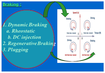
- Dynamic braking
- Rheostatic braking
- DC Injection braking
- Regenerative braking
- Plugging
Why Is Braking Required?
After switching off the AC supply, the motor keeps rotating for a definite period before reaching the standstill position.
This residual motion is due to the inertia of the rotating parts, which can take several seconds or more to come to rest depending on the load.
However, in case of an emergency or for some applications where coasting time is unacceptable, the motor must be stopped immediately.
To achieve this, various braking techniques are employed to bring the rotor to a halt quickly and safely.
DC Injection Braking Theory
When the AC supply is disconnected from the stationary stator, the VFD feeds DC supply to the stator winding. The DC supply produces a magnetic field that travels through the air gap and links to the rotor conductors.
This magnetic field is unidirectional and stationary, unlike the rotating magnetic field generated by AC.
Since the rotor is rotating at the moment of switching off the AC supply, the induced voltage in the rotor conductor causes electric current to flow in the short-circuited rotor conductors.
This current interacts with the stationary magnetic field, generating a braking force.
The speed of the rotor is more than the synchronous speed at the time of stopping the motor. In this condition, the motor works as a generator. It converts the rotational (kinetic) energy into electrical energy due to electromagnetic induction.
During the generating mode, the kinetic energy of the motor converts into electrical energy, which dissipates as heat energy in the rotor conductors. This process continues until the rotor speed reduces significantly.
This conversion and dissipation of electrical energy into heat energy produce braking torque in the motor, which allows it to stop quickly.
DC injection braking is highly effective for controlled and fast deceleration, especially in VFD-driven motors.
Circuit Diagram of DC Injection Braking
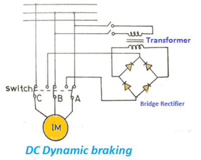
Circuit Description
The bridge rectifier converts AC voltage into DC. This DC voltage serves as the braking current source.
When we switch off the motor or the motor trips due to a fault, the changeover switch changes its position from the AC source to the DC source. This seamless switch ensures that braking action begins immediately after the AC power is cut off.
The stator winding of the motor now receives a DC supply.
We can select the number of windings receiving the DC by selecting one, two, or all the windings. Selecting all the windings produces more braking torque.
This is because more windings energized by DC generate a stronger stationary magnetic field, enhancing the braking force.
Various Stator Connections for DC Injection Braking
The stator winding, connected in a different configuration with a DC supply, produces the magnetic field for braking torque.
These connections determine how effectively the magnetic field interacts with the rotor to slow down its motion.
The magnitude of the torque depends on the DC magnitude and the stator winding configuration.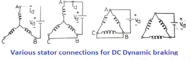
For instance, connecting all three stator windings can generate maximum braking torque, while using fewer windings results in lower torque output.
Hence, selecting the optimal stator connection is essential for achieving desired braking performance based on motor application and load conditions.
Braking Torque and Speed-Slip Characteristics
The induction motor can operate in three modes, i.e., motoring, generating, and braking. Each mode corresponds to a different range of slip values and torque behavior, which are critical for motor performance and control.
The following graph shows the speed-torque characteristics of the induction motor in the specified operating zones.
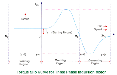
This graph helps visualize how torque varies with slip during motoring, generating, and braking operations.
The slip of the induction motor is more than 1 during the braking.
This condition indicates the rotor speed is lower than the synchronous speed in reverse, a requirement for effective dynamic braking.
With dynamic braking through DC injection in the motor’s stator, the braking torque depends on the magnitude of the DC.
A higher DC voltage results in a stronger braking torque. This torque helps the motor decelerate quickly and come to a controlled stop, which is essential in many industrial applications.
The DC must only be applied for a few seconds. The DC current produces the heating effect, I²R, in the rotor winding. The heating of the coil must be below its rated thermal limit; otherwise, the winding is likely to fail.
If DC voltage is applied for too long, it can overheat the winding and eventually lead to burnout.
To protect the motor, thermal overload settings or timers are often used to limit DC injection duration. Proper control and monitoring of braking time ensure safe and efficient operation of DC Injection Braking Of Induction Motor systems.
DC Injection Braking in VFD
The variable frequency drives are very popular, and we use VFDs for industrial and domestic applications.They offer precise motor speed control, energy savings, and enhanced braking features such as DC injection braking.
The VFD has an inbuilt function to generate DC output voltage. The DC voltage creates braking torque, which allows the motor to stop quickly. This braking method is particularly useful in applications where rapid deceleration is required, such as conveyors, fans, or lifts.
The block diagram of the VFD is given below. It illustrates how DC injection is integrated within the drive’s internal architecture for smooth and controlled braking.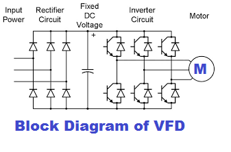
During DC injection, the inverter’s normal operation is disabled, and DC is injected into the stator winding by switching the IGBTs. The IGBTs act as electronic switches, enabling the controlled application of DC to the stator for producing the braking magnetic field.
Activating DC injection braking in a VFD is straightforward. Set the following parameters to enable DC injection braking.
Parameters Setting in VFD for DC Injection Braking
Activating DC injection braking in a VFD is straightforward. Set the following parameters to enable DC injection braking.
DC Injection Start Frequency
Set the frequency at which DC injection begins during a ‘ramp to stop’ operation.
This setting determines when the DC voltage will be applied as the motor slows down.
DC Injection Braking Current
Set the DC injection braking current to a percentage of the drive’s rated current.
Proper current setting ensures effective braking without overheating the motor.
DC Injection Braking Time at Start
Set the time of DC injection braking.
This controls how long DC is applied when the stop command is initiated.
DC Injection Braking Time at Stop
Set the time length of DC injection at the stop.
This duration ensures complete motor deceleration before power is fully removed.
The graph below shows the above parameters. It helps visualize how these settings affect braking torque, stopping time, and thermal limits. Adjust these carefully to balance performance and motor protection.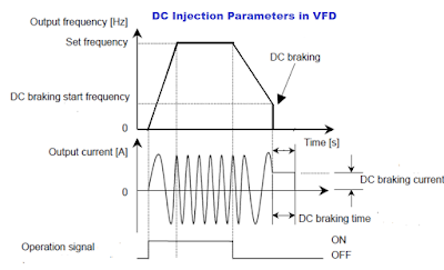
Related Articles: