Discover the concept of loop gain in electronics and control systems. Learn what is loop gain, how it affects feedback, stability, and performance in amplifiers, op-amps, and industrial control systems, with historical insights and design considerations.
What is Loop Gain? (Definition and Formula)
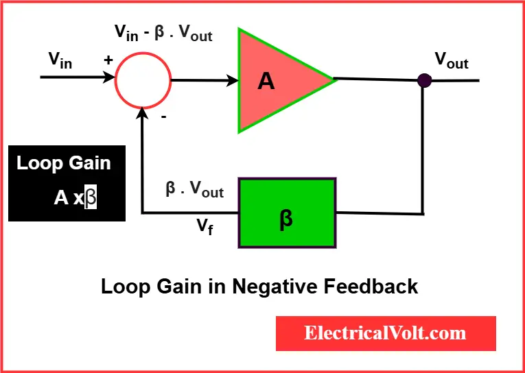
Loop gain is a fundamental concept in electronics and control system theory. It refers to the total gain around a feedback loop and plays a crucial role in how systems respond to inputs, manage feedback, and maintain stability. From amplifiers and oscillators in electronics to industrial automation and even biological systems, amplification loop is central to feedback-driven performance.
It is typically expressed as a ratio or in decibels (dB). Mathematically, if a system has a forward path gain A and a feedback path gain β, the loop gain (T) is given by:
T = A × β
If the feedback is negative (as in most amplifier and control system designs), the loop gain becomes:
T = −A × β
The negative sign indicates the feedback signal is subtracted from the input, which stabilizes the output.
How Loop Gain Works in a Feedback Loop
A feedback loop involves sampling the output of a system and feeding it back to the input to improve performance or stability. The strength of the feedback determines how strongly the output can influence the input.
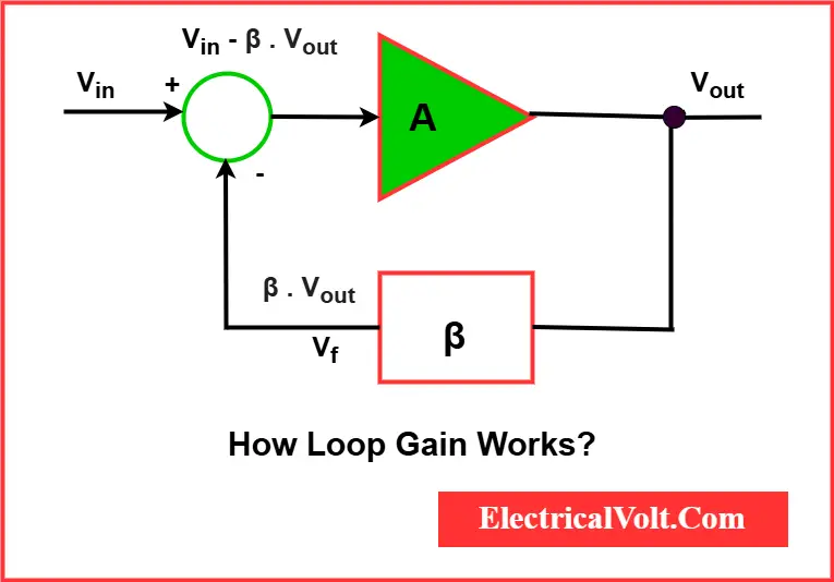
Let’s understand how loop gain works:
- The input signal enters the system.
- The amplifier boosts the signal with a gain of A (open loop gain).
- A portion of the output is fed back through a network with gain β.
- This feedback signal is subtracted from the input (negative feedback).
- The result is a controlled and often more accurate output.
The behavior of the feedback loop—whether it is stable, oscillatory, or unstable—depends significantly on magnitude and phase of the feedback gain.
A Bit of History
The importance of loop-based gain analysis was first identified by Heinrich Barkhausen in 1921 and was further refined by Hendrik Bode and Harry Nyquist at Bell Labs in the 1930s. Their foundational work helped establish gain in feedback systems as a key parameter in feedback system analysis.
Loop Gain in Electronics (Op-Amps, Amplifiers)
The concept is widely used in:
- Operational Amplifiers (Op-Amps)
- Power Amplifiers
- Oscillators
- Automatic Gain Control (AGC) circuits
Loop Gain Example: Op-Amp with Negative Feedback
In an op-amp circuit:
- A is the open-loop gain of the amplifier.
- β is the feedback fraction.
- The product A × β define the gain around the loop
As this product increases, the closed-loop gain becomes less dependent on the internal gain A and more dependent on external components (like resistors), improving precision and linearity.
What is Closed Loop Gain?
Closed-loop gain refers to the system’s overall gain once feedback is applied. In op-amps, it’s determined by the resistor network and is less sensitive to variations in internal amplifier gain.
Role of Loop Gain in Oscillation
For an oscillator to start and sustain oscillations, it must satisfy the Barkhausen Criterion, which has two conditions:
- Magnitude condition: ∣A⋅β∣=1 (i.e., total loop gain must be equal to one)
- Phase condition: ∠(A⋅β)=0∘ or 360∘ (i.e., the feedback signal must be in phase with the input)
If these conditions are met:
- The circuit will sustain oscillations.
- If ∣A⋅β∣>1|, oscillations grow.
- If ∣A⋅β∣<1, oscillations decay.
Check out our detailed guide on Barkhausen Criterion for Oscillator.
Loop Gain in Control Systems
In a control system—such as an automatic temperature controller or motor speed regulator—the feedback product is the product of the plant (forward path) gain and the feedback gain.
Let’s define it mathematically:
- G(s) is the forward path transfer function.
- H(s) is the feedback transfer function.
- Loop Gain L(s)=G(s)⋅H(s)
The closed-loop transfer function becomes:
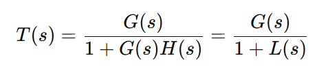
This equation determines how accurately and quickly the system reaches its desired output.In short, the feedback product governs both system stability and performance.
Frequency Dependence and Bode Plots
Gain is frequency-dependent, meaning it varies with the input signal’s frequency. That’s why it’s typically represented as:
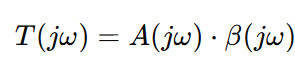
Where ω is the angular frequency in radians per second.
Loop Gain and Bode Plot
A Bode plot shows:
- Gain (in dB) vs frequency (on a logarithmic scale)
- Phase shift vs frequency
The leedback gain curve often appears as the difference between the A and the 1/β curve.
Key metrics derived from these plots include:
- Gain Margin
- Phase Margin
These margins indicate how close the system is to becoming unstable.
Real-World Control System Example
Consider a heating system in an industrial environment. A temperature sensor measures the current condition and feeds it into a controller. Based on the setpoint, the controller adjusts power to the heater.
This type of system uses feedback control to correct deviations. The amplifier and sensor combination defines how aggressively the system reacts. If the adjustment is too strong, the system may oscillate; if too weak, it responds sluggishly.
By tuning how much the system amplifies changes from the desired value and how much feedback is applied, engineers can achieve fast, stable regulation.
To compare feedback-based regulation with open-loop and feedforward control strategies, refer to Feedforward vs Feedback Control.
Block Diagram Explanation
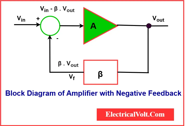
Imagine an amplifier block diagram with negative feedback to understand the loop-based amplification in electronics:
- Input goes to the amplifier with gain A.
- Output is fed into a feedback network with gain β.
- Feedback is subtracted from the input.
- Feedback strength = −Aβ
To analyze, engineers “break the loop” conceptually and calculate how much of an applied signal at that point would be amplified through the loop and return to the same point.
Characteristics and Importance of Loop Gain
| Feature | Explanation |
|---|---|
| Controls Stability | Ensures system doesn’t oscillate unintentionally. |
| Improves Accuracy | Helps systems reach and maintain desired output. |
| Enhances Linearity | Reduces distortion and non-linear behavior. |
| Extends Bandwidth | Boosts response over a wider frequency range. |
| Reduces Sensitivity | Minimizes the effect of component variation and noise. |
Design Considerations
While higher feedback gain is often desirable, it may:
- Reduce phase margin, risking instability.
- Affects transient response and settling time.
- Require compensation networks to balance performance.
Tuning via simulation and frequency analysis is essential to balance performance.
Conclusion
Loop gain in electronics and control systems is not just a technical parameter—it’s the heart of how feedback systems function. It governs everything from stability and accuracy to bandwidth and distortion.
Understanding loop gain allows designers to craft systems that are responsive, stable, and reliable, whether in a precision op-amp circuit, an industrial control system, or even biological feedback mechanisms.

Related Articles: