In this article, we will discuss the GMD (Geometrical Mean Distance) and GMR (Geometrical Mean Radius) in transmission lines, their definition, and their uses.
GMD (Geometrical Mean Distance) and GMR (Geometrical Mean Radius) are the two important terms used in the inductance and capacitance calculations of the overhead transmission lines. GMD and GMR simplify the transmission line inductance and capacitance calculations.
What is GMR?
GMR stands for Geometrical Mean Radius. GMR is also known as Self GMD or Self-Geometrical Mean Distance. GMR is usually denoted by the symbol DS.
The inductance of a transmission line per conductor per meter is given by,
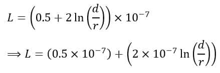
In this equation, the first term (0.5×10⁻⁷) is the value of inductance due to the magnetic flux present inside the line conductor. Therefore, GMR is the concept that can eliminate this term from the expression and makes the expression simple.
The process of eliminating (0.5×10⁻⁷) from the equation using the concept of GMR or self-GMD is as follows.
Consider, the solid line conductor is replaced by an equivalent hollow conductor having a very thin surface. Consequently, when an alternating current flows through this hollow conductor, the flux inside the conductor will be zero as it is a hollow conductor. Therefore, the term (0.5×10⁻⁷) will be eliminated from the equation.
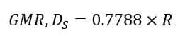
But, when we use a hollow conductor, the radius of the equivalent hollow conductor should be such that it can compensate for the internal flux by allowing space for additional flux. In practice, the hollow conductor’s radius is smaller than that of the solid conductor.
For example, if the radius of the solid conductor is “R”, then it is mathematically proved that the GMR of the conductor will be equal to 0.7788 times R.
After eliminating the term (0.5×10⁻⁷), the above equation will become,
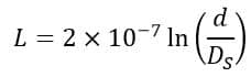
Where,
From this expression, it can be seen that the GMR of a conductor depends upon the shape and size of the conductor. But, the GMR does not depend upon the spacing between different line conductors.
What is GMD?
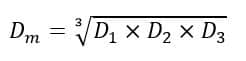
GMD stands for Geometrical Mean Distance. GMD is also known as mutual GMD because it is used in the calculation of the mutual inductance of the transmission line. It is often denoted by the symbol Dm.
The concept of GMD (Geometrical Mean Distance) simplifies the calculation of the mutual inductance of the bundled conductors. It is measured as the geometrical mean distance from one conductor to another conductor, that’s why it is called GMD. Since GMD is the distance between different conductors, thus it changes with the change in the arrangement of conductors.
Now, let us discuss the GMD (Geometrical Mean Distance) for different conductor arrangements.
(1). GMD of Two Adjacent Conductors (Single-Phase Line)
Consider two conductors that are placed adjacent to each other such that the spacing between them is very large as compared to the diameter of each conductor. Then, the mutual GMD or simply GMD will be equal to the distance between the centers of the conductors, i.e.

(2). GMD of Single Circuit 3-Phase Transmission Line
For a single-circuit three-phase transmission line, the GMD is given by,
Thus, the mutual GMD of a single-circuit three-phase line is equal to the equivalent equilateral spacing between conductors of the line.
(3). GMD of Double Circuit 3-Phase Transmission Line
A double-circuit three-phase transmission line has two three-phase circuits, i.e. three line conductors. Consider the arrangement of the double circuit three-phase transmission line as shown in the following figure.
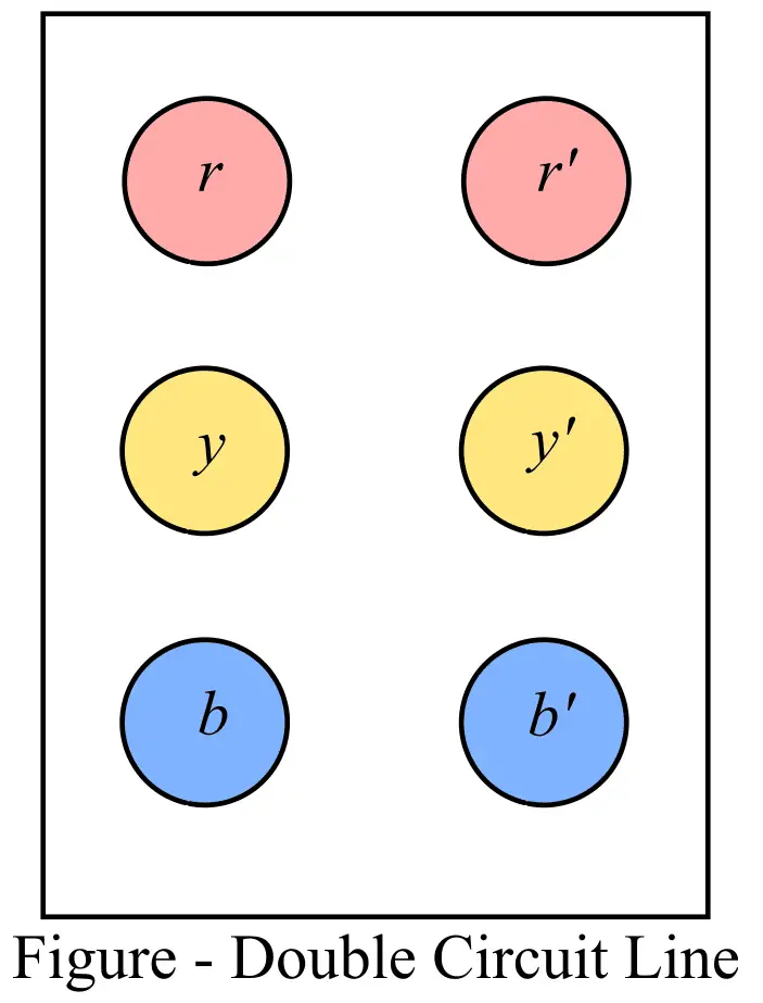
Here, the conductors r, y, and b belong to the first three-phase circuit, and the conductors r’, y’, and b’ belong to the second three-phase circuit.
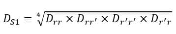
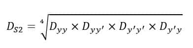
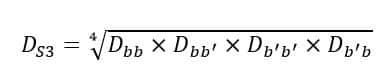
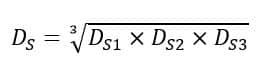
Thus, the GMR of the combination of the conductors rr’, yy’, and bb’, is given by,
For the first pair of conductors:
For the second pair of conductors
Similarly, for the third pair of conductors
Where,
- Drr = Dr’r’ = Dyy = Dy’y’ = Dbb = Db’b’ are the GMR of conductors.
- Drr’ = Dr’r, are the distance between conductors r and r’.
- Dyy’ = Dy’y, are the distance between conductors y and y’.
- Dbb’ = Db’b, are the distance between conductors b and b’.
Thus, the equivalent GMR per phase of the double circuit three-phase transmission line is,
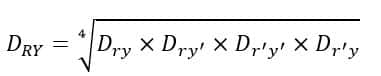
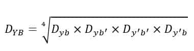
Now, let us calculate the mutual GMD among the phases RY, YB, and BR.
For phases RY, the GMD is given by,
For phases YB, the GMD is given by,
For phases BR, the GMD is given by,
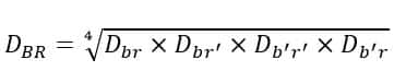
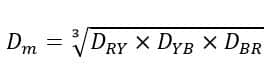
Thus, the equivalent GMD (Mutual GMD) is given by,
Note – The Mutual GMD (or GMD) depends upon the spacing among conductors, and it does not depend on the shape, size, and orientation of conductors.