Design considerations of Orifice Plate comprise factors like pipe size, flange rating, the material of orifice, Beta ratio, and location of the taps. Also, the fluid temperature, pressure, density, flow rate, properties, and Reynolds Number are very important parameters for designing the orifice plate. In this article, we will discuss these factors in detail.
We all know that the orifice plate is a primary sensing element for measuring flow. Various types of orifice plates are available. Now which orifice plate to be used or what are the factors we should consider before selecting an orifice plate. Let us discuss the important factors for the selection of orifice plate.
Design Factors of Orifice Plate Sizing
The following are the factors considered for orifice sizing.
- Size of Pipe
- Flange Rating
- Material of Construction of Orifice based on Fluid properties
- Pressure and flow rate of the fluid
- Density and temperature of the Fluid
- Beta Ratio
- Reynolds Number of the Fluid for selection of Orifice Plate type
- Location of Pressure Taps
Let us discuss each of the Orifice Plate Design Parameters in detail
1. Size of Pipe
The very first point we look at before selecting a flow meter is the pipe size. Orifice plate can be used from pipe size of 2 inches to 24 inches. Below a 2-inch line size, installing an orifice will create a problem of permanent pressure drop. Orifice generates a permanent pressure drop but for line size below 2 inches, the process will have an adverse effect. Orifice plates for line size greater than 24 inches, designing orifice plate is very difficult due to large size. Installing orifice plates in pipe sizes less than 2 inches and greater than 24 inches are special cases. Consulting vendors for such cases is very much important.
2. Flange Rating
Generally, orifice plates are available with different ratings from Class 150 rating to Class 2500 rating (ASME B16.36 standard for orifice flange dimensions). We should generally avoid Class 150 rating orifice. The reason is that the strength of the class 150 rating orifice is not good and it will not sustain the pressure and flow.
3. Type of Fluid (density and viscosity factor)
The type of fluid plays a very important role in designing an orifice plate. It can be liquid or gas or it can be a slurry as well. Type of fluid is required because this parameter is used for deciding the type of orifice plate. Also, the type of fluid decides whether to give a vent hole or drain hole for better performance of the orifice plate.
4. Material of Construction of Orifice based on Fluid properties
We measure the flow of different fluids. Each fluid has its own chemical properties. Hence it is clear that a single orifice plate cannot work for all fluids. That is the reason for considering the material of construction of orifice plate based on fluid properties. SS-316 is a widely used material for normal air and water flow measurement. Alloy 400 is most widely used in marine applications and desalination plants. This is because alloy 400 has very low rates of corrosion.
Alloy C276 has excellent corrosion resistance in both oxidizing and reducing environments. Therefore, alloy C276 is used in Chlorine applications.
5. Pressure and flow rate of the fluid
The flow and pressure have a square root relationship.
Flow Q ∝ √ΔP
Where, Q = Flow rate & ΔP = Differential pressure across orifice plate
Using an orifice plate means a permanent pressure drop in the process. Also, we know that pressure and flow are not directly proportional. The flow is proportional to the square root of the differential pressure generated by the orifice. Hence for lower flow, the differential pressure generated will be much less. This is the reason why we should use a differential pressure transmitter with an appropriate turndown ratio (generally 200:1). Thus, it is possible to achieve flow rangeability up to 10:1. Generally, the orifice plate produces differential pressure up to 5000 mmH20.
The flow rangeability above 10:1 is possible to achieve by;
- Use of two different capacities of orifice plates
- Use of two differential-pressure flow transmitters having different ranges
6. Beta Ratio
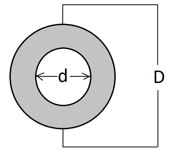
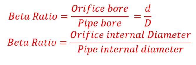
The beta ratio is a very important design factor for designing orifice plates. Generally, the beta ratio is kept from 0.3 to 0.75. This is because keeping very high means the orifice bore and pipe bore are nearly the same. Keeping the orifice bore and pipe bore nearly the same will not generate sufficient differential pressure. Also keeping the orifice bore too small will create too much pressure drop which is totally not acceptable. Hence beta ratio is a very crucial design factor.
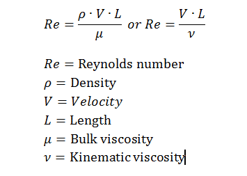
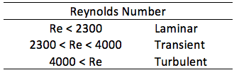
7. Reynolds Number of the Fluid for selection of Orifice Plate type
Reynolds number indicates the viscosity of the fluids and is expressed as;
Below are the types of orifice used for fluids with different Reynolds numbers.
| Type of orifice plate | Reynolds Number |
| Concentric | 80 to 1500 |
| Eccentric | 3000 to 12000 |
| Quadrant Edge | 1500 to 9000 |
| Segmental | 5000 to 20000 |
8. Location of Pressure Taps
Flange taps are generally used for orifice plates installed in small pipe sizes with sizes less than 2 inches. Corner taps are used for small pipe sizes but differential pressure is good enough. Pipe tapings are used when differential pressure is small. That is the reason for taking upstream tap at 2.5 pipe diameter upstream and 8 pipe diameters downstream. For pipe sizes greater than 6 inches, radius tapings are used.
Flange Taps
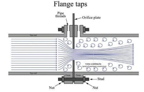
- Preferred for line size 2” and above
- The manufacturer of the orifice flange set drills the taps to have the centerlines 1 in. (25 mm) from the orifice plate surface.
- The flange taps are not suitable below 2 in. (50 mm) pipe size and cannot be used below 1.5 in. (37.5 mm) pipe size, because the vena contracta may be closer than 1 in. (25 mm) from the orifice plate.
Vena Contracta taps
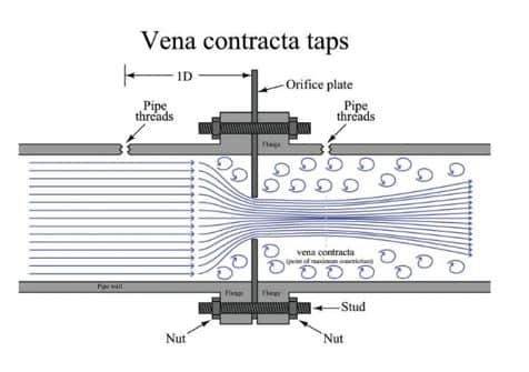
- Taps at 1D upstream and a downstream tap location are at the point of minimum pressure.
- Vena contracta taps offer the greatest differential pressure for any given flow rate, but it requires a precise calculation for the proper location of the downstream tap position.
Radious Taps
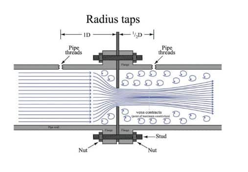
- Radius taps are suitable for large pipe sizes (one-half pipe diameter downstream for the low-pressure tap location). It is the approximate equivalent of Vena Contracta taps.
- An unfortunate characteristic of both the taps requires drilling through the pipe wall.
- The drilling through the pipe wall weakens the pipe, but it is the requirement for ensuring measurement accuracy.
Corner Caps
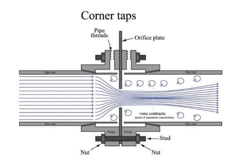
The corner taps are suitable for small pipe diameters because vena contracta is very close to the downstream face of the orifice plate, and the downstream flange tap would sense pressure in the highly turbulent region.
Related Articles: