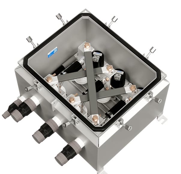
Link box, a box in which a cable sheath braking system is made. Sheath breaking prevents circulating currents and limits induced voltage in the cable sheath using bonded systems up to 132kV.
Underground medium & high voltage cable bonding have sheaths to provide cable sheath bonding to reduce the circulating sheath currents. Cable sheath bonding limits the induced cable sheath voltages for safety reasons.
A cable has mainly three main parts.
- Conductor
- Insulation
- Sheath
The conductor has very low resistance and carries the current. Insulation is coated around the conductor to provide isolation between conductor and sheath.
The sheath is coated around the insulation. The insulation over the sheath provides the additional coating that enhances the cable protection.
Low voltage cables do not have sheaths. However, MV & HV cables have sheaths to provide protection against over-voltage & transients.
The sheath also prevents moisture ingress from the surrounding environment to the main insulation. Thus, it enhances the useful life of the cable insulation.
How does Voltage Induce in the Sheath?
Any current-carrying conductor sets up a magnetic field around it. The magnetic field is varying in nature and it can produce a voltage in the metallic material. Thus, the magnetic field links to the metallic sheath and induces a voltage.
The induced voltage causes a leakage current to flow, and it causes losses in the power cable.
Solution for Minimization of Sheath Induced Voltage
We install Link boxes in association with cable joints to provide bonding of the HV cable circuit. Now, we will discuss what are the link boxes.
Link Boxes
Link boxes have a sealed, weatherproof design for bonding cable and joints/terminations. We use link boxes for;
- To nullify the voltage induced in the sheath
- To minimize cable losses caused by the sheath circulating current
Connection Diagram in Link Box
As discussed earlier in this post, the power cable has a conductor, insulation & sheath. We can nullify the voltage induced in the sheaths by transposing the sheaths of all three phases.
We take a part of the sheath layer of each phase cable and, connect the sheath layers in the link box as shown below.
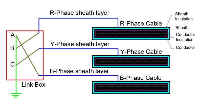
The one end of the sheath bonding cable has a connection with all three sheaths and, another part of the sheath cable has its connection to grounding earth.
By connecting the sheaths to the earth, We can minimize the induced voltage to almost zero. And, the cable losses on account of sheath losses reduce drastically.
For a long power cable, we the boxes at equal interval distance from the source end to load end. The cable runs continuously over the entire length, and only part of the sheath is cut at regular distance intervals. This leads to the minimization of sheath power losses in the cable.
Link Box Types
These are of two types.
- single bonding and
- Cross bonding
Applications of Link Box
The followings are the applications.
- Limits voltage build up on the sheath & minimize Sheath circulating current
- As a voltage limiter( Limits the lighting & switching surges)
- Provide easy access to shield breaks for test purposes
Read Next: