The phenomenon of cogging and crawling in induction motor happens due to improper motor design or operation by feeding the harmonic-rich supply source. The adverse effects of cogging and crawling can be minimized by proper motor design and ensuring the motor is not operated on a harmonic-rich supply such as an improperly tuned VFD.
Cogging in Induction Motor
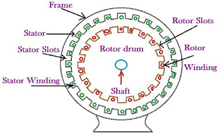
The phenomenon of magnetic locking created between the stator and the rotor teeth is called cogging.
It occurs when the rotor aligns with the stator slots in such a way that it prevents the motor from developing starting torque, resulting in a locked or stalled rotor.
The motor may refuse to deliver the torque because of the magnetic locking between the stator and rotor teeth, caused by the minimum reluctance, especially if the number of stator slots is equal to or an integral multiple of the rotor slots.
The reluctance is minimum when the stator slots are equal to or a multiple (or integral multiple) of the rotor slots.
Conditions Causing Cogging in Induction Motor
The following factors contribute to this condition:
- Harmonic-Slot Frequency Interaction: If the harmonic frequency in the supply coincides with the slot frequency of the motor, it results in torque modulation. This interaction can create a magnetic locking condition, preventing the rotor from developing sufficient starting torque—this refusal to start is referred to as cogging or teeth locking.
- Rotor and Stator Slot Alignment: When the number of stator slots equals or is an integral multiple of the rotor slots, the magnetic reluctance becomes minimum, and the stator teeth align perfectly with the rotor teeth. This causes magnetic locking between the stator and rotor, leading to cogging.
- Permanent Magnet Interaction: In motors that use permanent magnets, such as BLDC or PMSM, improper alignment of magnetic poles with stator slots can create an unbalanced magnetic pull, resulting in a resistance to rotation at startup—a form of cogging.
- Rotor Design Influence: The design of the rotor, especially in relation to slot count and geometry, plays a critical role. If the rotor slot design allows it to lock into the stator slots magnetically, cogging is more likely.
- Uneven Air Gap: Variations in the air gap between the stator and rotor can produce uneven magnetic forces. This non-uniformity contributes to irregular torque and may further enhance the cogging effect.
How to Reduce the Cogging in Induction Motor
Cogging can be effectively minimized through motor design and construction techniques. The following measures help in eliminating or reducing cogging:
- Unequal Slot Count: Ensure that the number of stator slots is not equal to the number of rotor slots. This prevents the alignment that causes magnetic locking between the stator and rotor teeth.
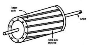
- Skewing of Rotor Slots: The rotor slots should be skewed—that is, made non-parallel to the shaft axis. Skewing disrupts the alignment between stator and rotor slots throughout the rotor’s length, reducing the locking tendency and enabling smoother starting.
- Optimize Permanent Magnet Placement: In motors using permanent magnets, optimizing the placement of the magnets ensures better magnetic alignment with the stator slots, which helps minimize torque ripple and cogging.
- Modify Rotor Geometry: Adjusting the rotor design, especially in permanent magnet motors, can help achieve a more uniform magnetic field distribution. Design changes such as fractional slot winding and tailored slot shapes are commonly used to reduce cogging torque.
Rotor and Stator Slot Harmonic Order
The stator slot harmonics depend on the number of stator slots and poles. The stator generates slot harmonics of order 2Ss/P ± 1, and the rotor produces harmonics of order 2Sr/P ± 1, where Ss and Sr are the numbers of the stator and rotor slots, and P is the number of poles.
If the number of stator and the rotor slots are equal for a particular number of poles in the machine, the harmonic order produced will be the same.
Suppose the stator and rotor slot harmonic order are 11th and 13th. The 11th harmonic produces a backward-rotating field, and the 13th harmonic generates a forward-rotating field.
If the 11th harmonic order produces the same backward-rotating field, it is only if the rotor speed is zero. The field produced by the 11th slot harmonic order would be stationary when,
nr-(ns-nr/11)=-ns/11
nr=0 ——–(1)
The 13th slot harmonic order produced by the stator and the rotor would be stationary if;
2Ss/P+1 = 2Sr/P+1
Ss = Sr ——-(2)
2Ss /(P-1) = 2 Sr/(P+1)
Ss-Sr =P ——–(3)
Where Ss and Sr are the stator and rotor slots, respectively, P is the number of poles.
From above, it is clear that the cogging phenomenon will happen if ;
- The number of rotor slots is equal to the number of stator slots.
- The difference between the stator and the rotor slots equals the number of poles.
The above points are considered while designing the motor to avoid cogging.
Why Cogging Does Not Occur in Slip-Ring Induction Motors
In an induction motor, the rotor bars are spaced apart, and the conductor has wider spacing. The torque produced is uneven throughout the revolution. By skewing the rotor bars, the cogging phenomenon can be reduced to a greater extent.
The rotor winding is distributed through slots in a slip ring or wound rotor induction motor. The wound rotor has a higher number of closely spaced slots than the slots of the squirrel cage induction motor.
This arrangement of wound rotors produces an even magnetic field and generates more torque throughout the revolution, and thus, cogging is eliminated.
Crawling in Induction Motor
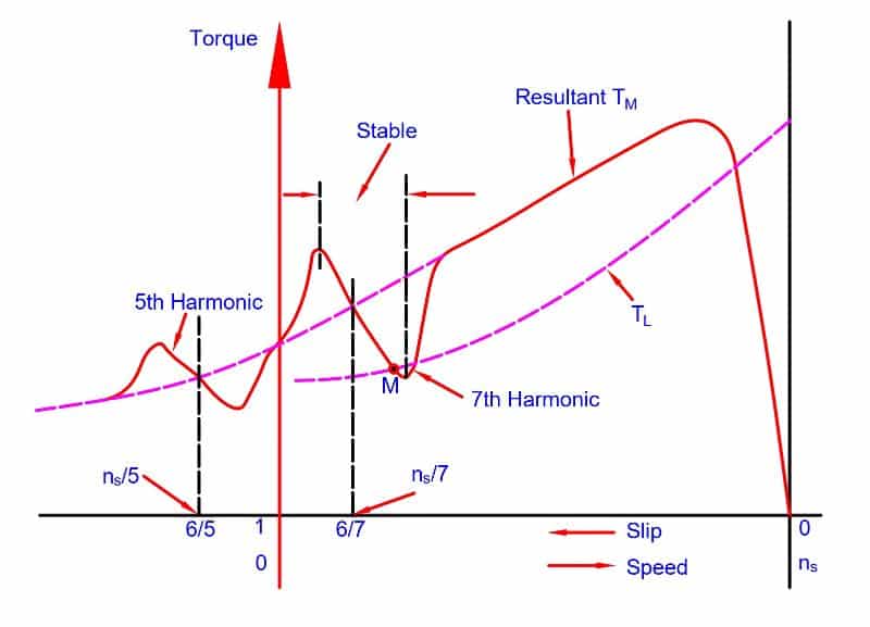
Crawling in an induction motor is a phenomenon where the motor runs at a very low speed (typically around 1/7th of its synchronous speed) due to the influence of harmonic torques, especially the 7th and 13th harmonics.
When the induction motor is operated with a VF drive, the VFD introduces both even and odd-order harmonics. The harmonic currents produce a rotating magnetic field in the stator, and the flux links with the rotor.
As a result, the current starts flowing in the rotor, which generates both positive and negative torque relative to the fundamental supply.
The torque contributions from different harmonic orders, both positive and negative, influence the net torque of the motor. The resulting drop in net torque reduces the efficiency of the motor.
The order of harmonics and the phase sequence of harmonic current are given below.
| Harmonic Order | 1 | 2 | 3 | 4 | 5 | 6 | 7 | 8 | 9 | 10 | 11 | 12 |
| Phase Sequence | + | _ | 0 | + | _ | 0 | + | _ | 0 | + | _ | 0 |
The phase sequence of the 5th harmonic order is opposite to the phase sequence of the fundamental current. The fundamental current produces the positive torque, and the 5th harmonic order current produces the negative torque.
Thus, in this condition, the net torque of the motor is always less than the torque produced by the fundamental current.
Similarly, the 7th harmonic order’s current produces positive torque, and the synchronous speed of the 7th harmonic order is equal to one-seventh of the fundamental synchronous speed (Ns/7).
If the torque demand is low, the motor may settle into a stable operating point at this reduced speed.
For example, a motor with a 1500 RPM synchronous speed can continue running at approximately 214 RPM (1500 ÷ 7), and may fail to accelerate beyond this due to harmonic locking.
This phenomenon, where the motor operates at a much lower speed than its rated speed, is known as crawling. The motor can crawl at Ns/7 due to the 7th harmonic, and it can also crawl at Ns/13 due to the 13th harmonic.
How the 7th and 13th Harmonic Orders Cause Crawling in Induction Motors
The motor’s slip at 5th and 7th order harmonic frequency is expressed below.
s = (Ns- N)/ Ns
The synchronous speed of the motor for fundamental frequency is Ns and equals 120f/P. The synchronous speed of 5th-order harmonics;
( f5=250 Hz) =120*(f5/P)= Ns/5
The 5th harmonic produces a backward rotating field, so its synchronous speed is negative:
The slip of the motor at 5th order harmonics:
s(5f)= Ns- (-Ns/5)/Ns
s(5f) =1.2
As the slip is more than unity, the 5th-order harmonics will exert negative torque on the rotor.
The slip at the 7th harmonic order
s(7f) = Ns- (Ns/7)/Ns
s(7f) = 6/7
s(7f) = 0.857
The slip at the 13th harmonic order
s(13f) = Ns- (Ns/13)/Ns
s(13f) = 12/13
s(13f) = 0.923
If the torque requirement is low, the motor can stably operate at a slip of 0.857 or 0.923 corresponding to the 7th and 13th-order harmonic frequencies.
A 1500 RPM motor can settle into stable operation at approximately 214 and 115 RPM for the 7th and 13th-order harmonic frequencies, respectively. The operation of an induction motor at such low RPM is known as crawling.
The torque slip characteristics of the induction motor for harmonics order frequencies are given below.
The overall efficiency of the motor operating under harmonic currents deteriorates because they reduce the motor’s torque and increase heating due to higher copper losses.
Suppose the sum of the negative torque produced by negative phase sequence harmonics exceeds that of the fundamental (positive) torque-producing current. In that case, the net torque may not be sufficient to drive the equipment, and the motor may refuse to start.
The crawling and cogging are not predominant in slip-ring induction motors. The cogging and crawling are almost absent in wound rotor or slip ring induction motors.
Why Crawling Does Not Occur in Slip-Ring Induction Motors
The slip ring or wound rotor induction motor produces significantly more torque than the squirrel cage induction motor. The external resistance added to the rotor circuit boosts the torque of the motor. Thus, the motor quickly passes through the 1/7th and 1/13th synchronous speed regions, and eliminates the crawling effect.
Solved Example: Cogging and Crawling in Induction Motor
A three-phase 440 volts, 6 poles,50Hz squirrel cage induction motor has the following design data.
- The gross length of the stator = 0.20 m
- Number of stator slots = 45
Calculate the number of rotor slots for cogging-free operation.
To avoid cogging,
Ss > Sr
Sr # Ss
The rotor slots must be less than 45.
Ss – Sr ≠ ±3P
Sr –±3P ≠ ±Sr →45 -3 x6 → 45 -18 →27
To avoid synchronous hooks and cups in slip torque characteristics
Ss – Sr ≠ ±P, ±2P, ±5P
Ss – Sr ≠ (45 – 6), (45 – 12), (45 – 03) ≠ 39, 33, 15
To avoid noisy operation
Ss – Sr ≠ ±1, ±2, (±P ±1), (±P ±2)
Ss – Sr ≠ (45 – 1), (45 – 2), (45 – 7), (45 – 8)
Ss – Sr ≠ 44,43,38,37
Considering all the above conditions, Sr = 42.
Conclusion
Cogging and crawling are two undesirable effects in squirrel cage induction motors that originate from harmonic distortion and improper motor slot design.
Cogging leads to magnetic locking and prevents the motor from starting, while crawling results in the motor operating at sub-synchronous speeds due to harmonic-induced torque dips.
These issues can be minimized or eliminated by skewing rotor slots, avoiding equal stator and rotor slot numbers, and managing harmonic-rich power sources like improperly tuned VFDs.
Slip-ring or wound rotor induction motors inherently mitigate these effects due to their rotor construction and torque-enhancing external resistance.
Related Articles: