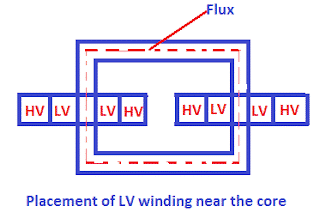
In a transformer, the LV (Low Voltage) and HV (High Voltage) windings are arranged strategically for performance and safety. One common design is to place the LV winding near the core.
The LV winding is placed next to the core because, with this arrangement, we get the advantage of reduced insulation, low leakage reactance, and easy placement of the tap changer at the outer HV winding.
This article explains the technical reasons behind placing the LV winding next to the core, including insulation efficiency, leakage reactance, and tap changer convenience.
Understanding HV and LV Windings in Transformer
First, let’s understand the basic concept so that we can understand why the LV winding is placed near the core.
In a three-phase transformer, the primary and secondary winding are placed around the core.
The cross-section area of the high-voltage (HV) winding conductor is less than that of the low-voltage (LV) winding, and to transfer the same power from primary to secondary, the voltage is stepped down at the secondary end.
As a result, the current in the secondary will increase in the same proportion as the reduction of the secondary voltage.
Example: LV and HV Side Currents in Transformer
For example – A transformer with a delta star configuration of rating 6.6/0.440 KV, 50 Hz, 1500 KVA,
The ratio of primary to secondary voltage (line-line)=6600/440= 15——— (i)
Primary line current Ip = 1500*1000/ √3 *6600 = 131 Amp.
The line current on the secondary side will be 15 times higher than that of the primary. This is because the voltage is reduced to 1/15th, causing a proportional increase in current.
Line current at secondary side = 131 *15= 1965 Amp.
From the above example, it is clear that the current rating of the low-voltage side of the transformer is higher than the current at the high-voltage side.
Leakage Reactance in Transformer HV and LV Windings
When the primary winding of the transformer is connected to the supply, the current flowing in the primary winding produces a magnetic field and induces flux in the core. The flux travels through the magnetic core and links to the secondary winding.
However, practically, not all of the flux produced in the primary links to the secondary. The flux that does not link is called leakage flux.
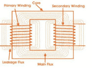
The reason for the leakage inductance is that the flux between primary and secondary winding is not perfectly coupled.
The flux produced in the primary does not link to every turn of the secondary, and some parts of the flux remain unlinked to the secondary and, it introduces leakage inductance in series with the primary and secondary winding of the transformer.
The higher the leakage inductance is, the lower the regulation of the transformer.
Why LV Winding is Placed Near the Transformer Core?
There are two main reasons for placing the LV winding near the core:
- Reduced insulation requirement
- Lower leakage reactance
Insulation Requirements for LV and HV Winding
In the concentric arrangement of placing HV and LV winding, less insulation is required when LV winding is placed near the core, which is at ground potential.
In this configuration, the HV winding surrounds the LV winding and is typically equipped with a tap changer to regulate output voltage.
If the HV winding is placed near the core, thicker insulation is required between the core and the winding, increasing transformer size and cost.
For the same rating of transformer, if high voltage winding is placed near the core, more insulation will be required. More insulation leads to an increase in the size and cost of the transformer.
If low-voltage winding is placed near the core, the size and cost of the transformer are reduced.
In a core-type transformer, the LV winding is always placed near the core. In a shell-type transformer, HV and LV winding are interleaved alternately to reduce the leakage flux.
Let us understand the insulation requirement in the core-type transformer after the placement of winding in different ways.
Insulation Calculation Based on Winding Placement
Let the transformer voltage rating be 132/6.6 KV. The low-voltage winding is placed near the core, and the high-voltage winding is placed after LV placement.
Case 1: If LV Winding is Placed Near the Core
The insulation required for LV =
Insulation required to insulate LV and Core + Insulation required to insulate HV and LV winding.
The insulation required for LV = 6.6 + (132-6.6) =132 KV
Case 2: If HV Winding is Placed Near the Core
The insulation required for HV =
Insulation required to insulate HV and Core + Insulation required to insulate HV and LV winding
The insulation required for HV = 132 + (132-6.6) =257 KV
Percentage increase in insulation = (257-132)/132 x 100 = 94.69 %
Thus, the increase in insulation results in an increase in the cost and size of the transformer.
How Winding Placement Affects Leakage Reactance
The leakage reactance depends on the distance between the core and the HV winding.
When the HV winding is placed farthest from the core, the leakage reactance of the primary is low. The low leakage reactance means most of the flux produced in the primary winding gets linked to the secondary.
The inrush current of the transformer gets reduced. Furthermore, the voltage regulation of the transformer is improved.
Tap Changer Placement on the HV Side of a Transformer
The tap changer is placed on the high-voltage side of the transformer. The current flowing in the HV winding is low; hence, there is less wear on the tap changer contacts.
Also, it is easy to bring the connections of the HV winding at the tap changer because the cross-section area of the connecting lead is less.
If the tap changer is connected to the LV side of the transformer, a large cross-section area conductor is needed, and there would be more contact wear of the tap changer contact because of more current.
Thus, placing the low voltage winding near the core and high voltage winding after low voltage winding facilitates ease of tap changer connections at high voltage winding.
This arrangement results in longer life of the transformer tap changer.
Summary: Benefits of LV and HV Winding Arrangement
Placing the LV winding near the core offers insulation savings, reduces leakage reactance, and facilitates a longer life for the transformer by easing the design of the tap changer system.
FAQs
The LV winding is placed next to the core to reduce insulation requirements, minimize leakage reactance, and simplify tap changer placement on the HV side.
If the HV winding is near the core, thicker insulation is required, increasing the size and cost of the transformer. It also affects efficiency and design complexity.
Placing the LV winding near the core and HV winding on the outside reduces the leakage reactance, which improves voltage regulation and transformer performance.
Yes. In core-type transformers, the LV winding is placed near the core. In shell-type transformers, HV and LV windings are interleaved to reduce leakage flux.
Because current is lower on the HV side, placing the tap changer there reduces wear and allows for smaller conductor sizes, improving durability and ease of connection.
Realted Articles: