The torque-slip characteristics of an induction motor are essential for understanding how the motor behaves under various load conditions. These characteristics help evaluate how slip influences the torque produced, determine stability zones, and understand performance during motoring, braking, and generating modes.
This article explains all three operating zones in detail, starting with a clear understanding of slip and its role in motor performance.
What Is Slip in an Induction Motor?
The speed of the induction motor is characterized by the term known as slip. Slip is defined as the ratio of the difference between the synchronous speed and the actual rotor speed to the synchronous speed of the induction motor.
The slip of the motor is expressed with the following formula.
s= (Ns-N)/Ns
Percentage slip = (Ns – N)/Ns × 100
Where:
Ns = 120f/P – Synchronous speed
N– The actual speed of the motor
For example, if the synchronous speed of induction motor is 1500 RPM and the rotor runs at 1450 RPM, the slip can be calculated using the formula:
Slip (%) = [(Ns – N) / Ns] × 100,
= [(1500 – 1450) / 1500] × 100 = 3.33%
Torque-Slip Curve: Unstable and Stable Zones
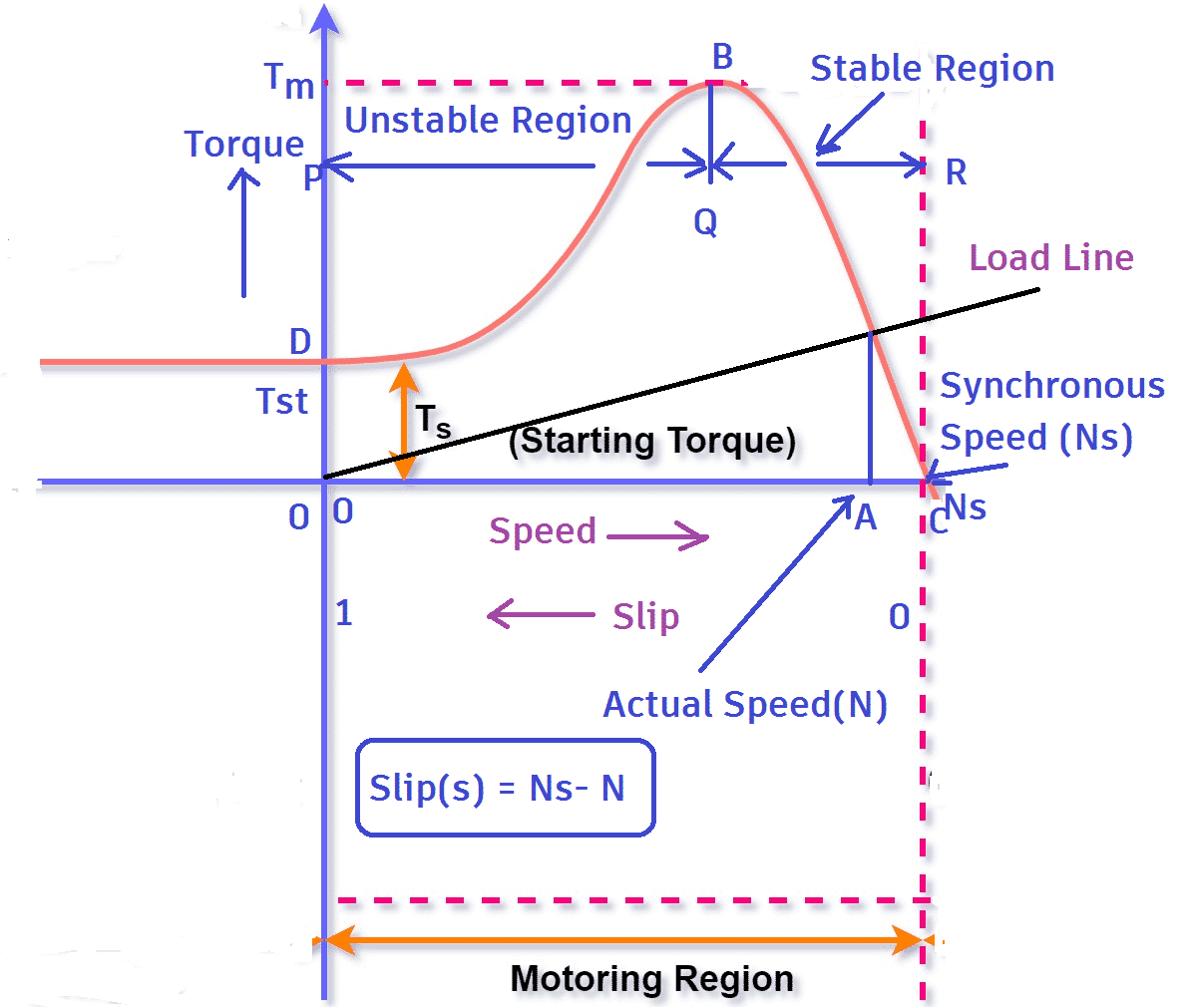
In the region from D to B, the motor produces pull-up torque to accelerate the load. This region is the unstable zone of operation. If the load torque line falls in this zone, the motor will fail to drive the load and may stall.
If the load torque line falls beyond point B, the motor will reach a stable point of operation. The QR region is the stable zone of operation.
This torque-slip curve helps visualize both stable and unstable behaviors and is a key part of induction motor characteristics.
Significance of Torque Slip Characteristics
The torque-slip characteristics of an induction motor are crucial for evaluating the motor’s performance under various operating conditions. Understanding this curve helps in:
- Determine stable and unstable zones during motor startup and full-load operations.
- Select suitable motors for different applications like pumps, conveyors, or regenerative systems.
- Predict behavior during motoring, braking, and generating modes.
- Prevent stalling by analyzing the shape of the torque-slip curve under load conditions.
- Design efficient control strategies for variable speed drives and load matching.
Methods of Varying Slip
The slip of the induction motor, and thus its speed, can be changed using the following methods.
- Adding external resistance in series with the rotor winding
- Adding external resistance in the series with the stator winding
- Reducing stator voltage by autotransformer
Operating Zones of Induction Motor & Torque-Slip Characteristics
The torque of the motor also changes with the change in slip. The torque speed characteristics of induction motor clearly explain its performance for a particular load.
The induction motor can be operated in three zones of operation by controlling the slip. These are,
1. Motoring Zone
2. Generating Zone
3. Braking Zone
The torque-slip characteristics of induction motor across different operating zones is given below.
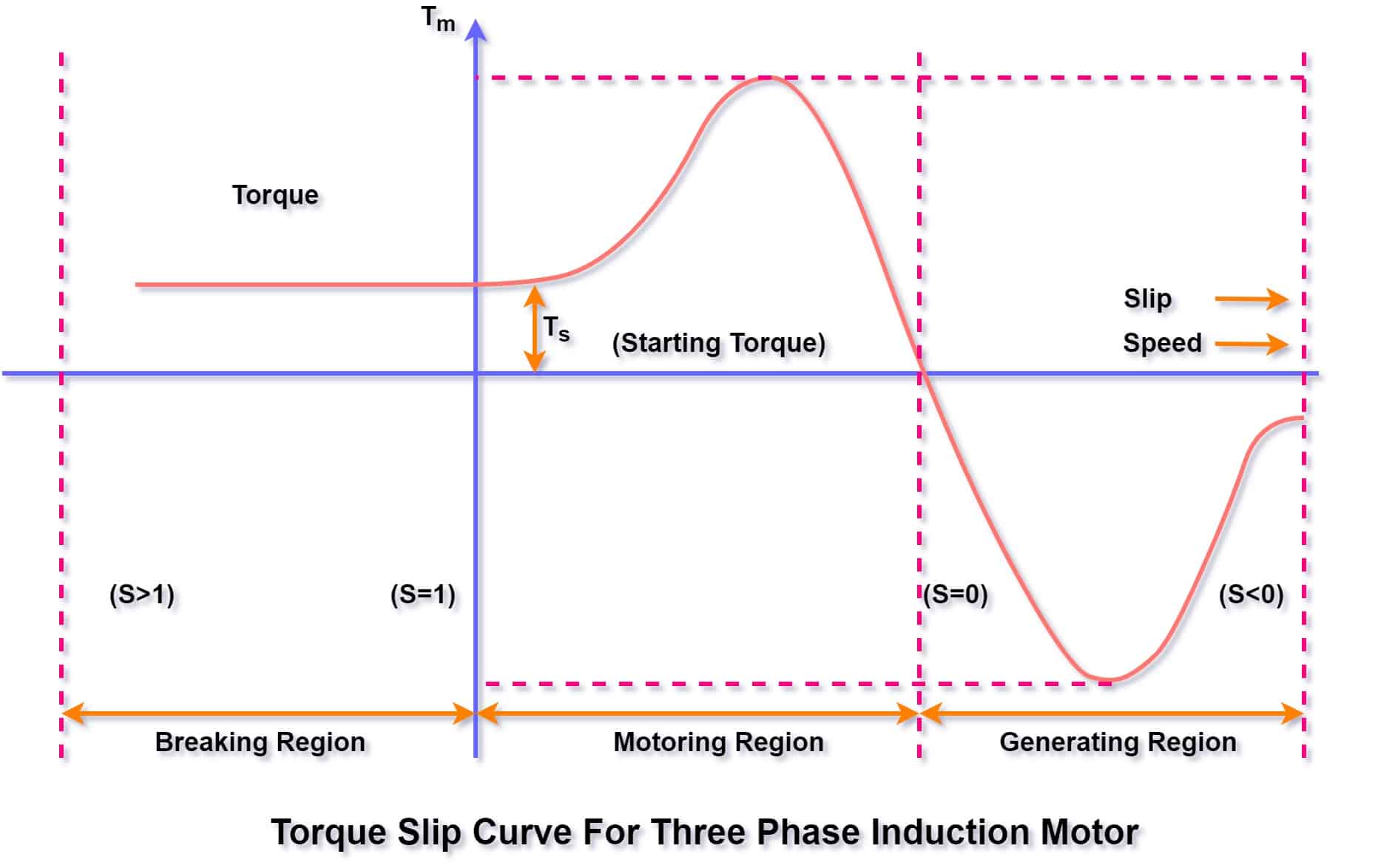
Torque-Slip Characteristics in Motoring Mode
In motoring mode, the slip of the induction motor ranges between 1 and 0.01. The slip can’t be zero; if it were, no torque would be produced, and the motor would not rotate.
When the rotor is at rest, the slip is 1. As the motor accelerates from rest to its rated base speed, the slip gradually decreases.
The starting torque of the motor is low because the rotor impedance is more inductive due to higher slip and higher rotor frequency.
As the motor accelerates, the induced voltage in the rotor and the slip decrease, improving the torque-delivering capacity. When the motor torque meets the load torque curve, a stable operating point is achieved.
In this mode, both speed and torque are positive. It is very important to study the moment of inertia (GD2) of the load before selecting the motor.
The speed-torque curve of the driven equipment should be submitted to the motor manufacturer so that the torque speed characteristics of induction motor can be matched appropriately with those of the driven equipment.
For related startup issues, also read: Cogging and Crawling in Induction Motor
Torque-Slip Characteristics in Generating Mode
In this operation mode, the induction motor runs above its synchronous speed.
This condition occurs when the rotor of the motor is connected to a prime mover and driven beyond synchronous speed. The motor works as an induction generator.
Another condition for generating mode occurs when the supply frequency is reduced, but the actual motor speed remains high due to a high-inertia load. This condition occurs when the motor is driving loads with high inertia.
Both the slip & and torque of the motor are negative in generating mode.
This mode illustrates the significance of torque slip characteristics in regenerative applications.
Torque Slip Characteristics in Braking Mode
In the braking mode of operation, the slip of the motor is greater than unity.
If the actual speed of the motor is greater than the synchronous speed , the motor works as a generator. When the motor dissipates its rotating kinetic energy as heat, it produces a braking torque, which reduces the motor speed.
This braking behavior is another important part of induction motor characteristics to consider in dynamic applications.
Summary Table: Torque-Slip Operating Zones of an Induction Motor
| Operating Zone | Slip Range (s) | Typical Applications |
| Motoring Mode | 0 < s < 1 | Fans, pumps, compressors, conveyors |
| Generating Mode | s < 0 | Regenerative braking, wind turbines |
| Braking Mode | s > 1 | Elevators, cranes, dynamic braking |
Common Braking Methods in Induction Motors
The various braking methods used for induction motors are as follows.
- Dynamic Braking
- DC injection braking
- Regenerative braking
- Plugging
Also read: Types of Braking in a DC Motor
Related Articles: