Electricity is the driving force behind nearly everything we use, from smartphone chargers to heavy industrial machinery. To grasp how it moves through circuits, we begin with a key concept called Ohm’s Law, which describes the connection between voltage (V), current (I), and resistance (R) in a conductor.
In this guide, we’ll explore Ohm’s Law in depth—covering its definition, formula, derivation, experimental setup, practical examples, real-world applications, and limitations—explained in a straightforward way for easy understanding.
What is Ohm’s Law?
Ohm’s law states the relationship between the potential difference and current in the circuit. The current in the circuit depends on the voltage and its circuit resistance. The Ohm’s law establishes the relationship between current, voltage, and resistance. Georg Simon Ohm experimented to find the relationship between the electric current and voltage.
Ohm concluded after his experiment that the current flowing in the circuit is proportional to the potential difference across the conductor. This relationship between current and voltage is known as Ohm’s law. We will also discuss this law where it is not applicable to which types of devices.
Ohm’s Law Statement & Definition
Ohm’s law states that the current flowing in the circuit is;
- Proportional to the voltage applied across the circuit, if the temperature is constant.
Why temperature is kept constant in Ohm’s law?
The resistance increase with an increase in the temperature depending on the temperature coefficient of the resistance. The current flowing in the circuit is I = V/R. If the resistance does not remain constant, the current will change and Ohm’s law is not valid in this case. Therefore, during the experiment for establishing the relationship between voltage and current, the temperature must be constant.
Ohm’s Law Explanation
When we increase the voltage across the conductor, the current also increases in the same proportion of the potential difference across the conductor. The conductor has definite resistance. We denote the resistance by the symbol ‘R’. Unit of resistance is Ohm. Its symbol is Ω.
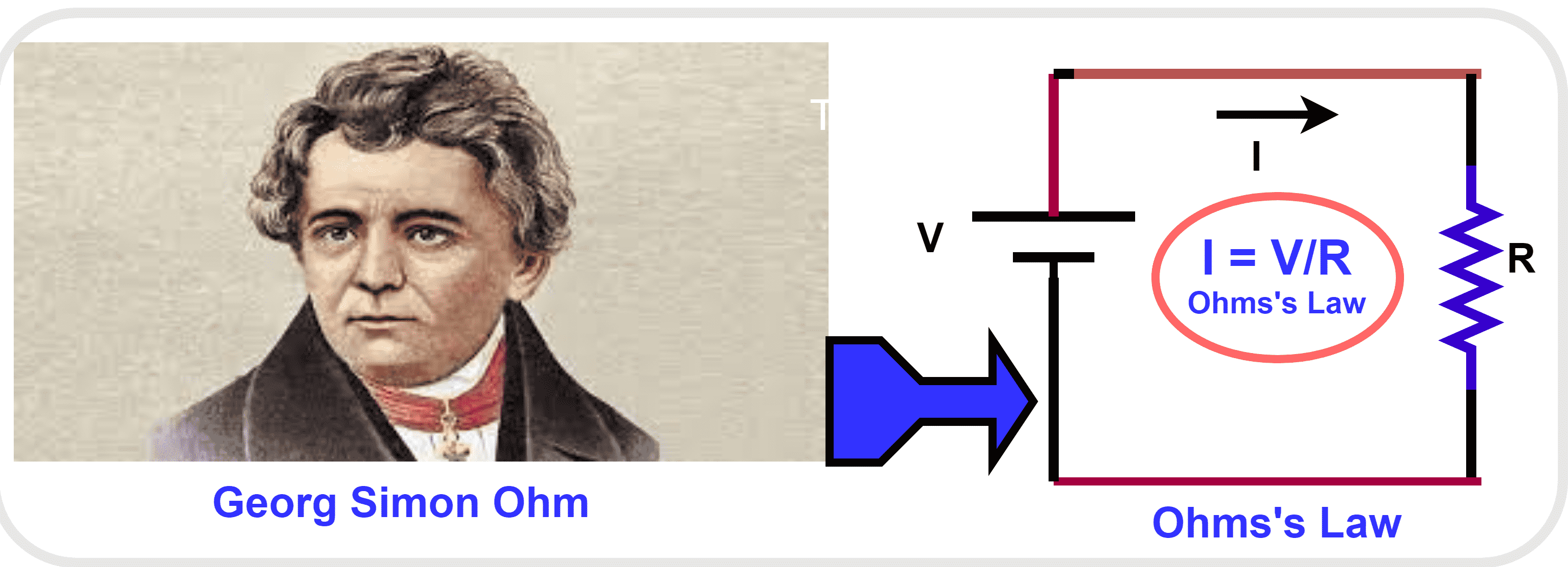
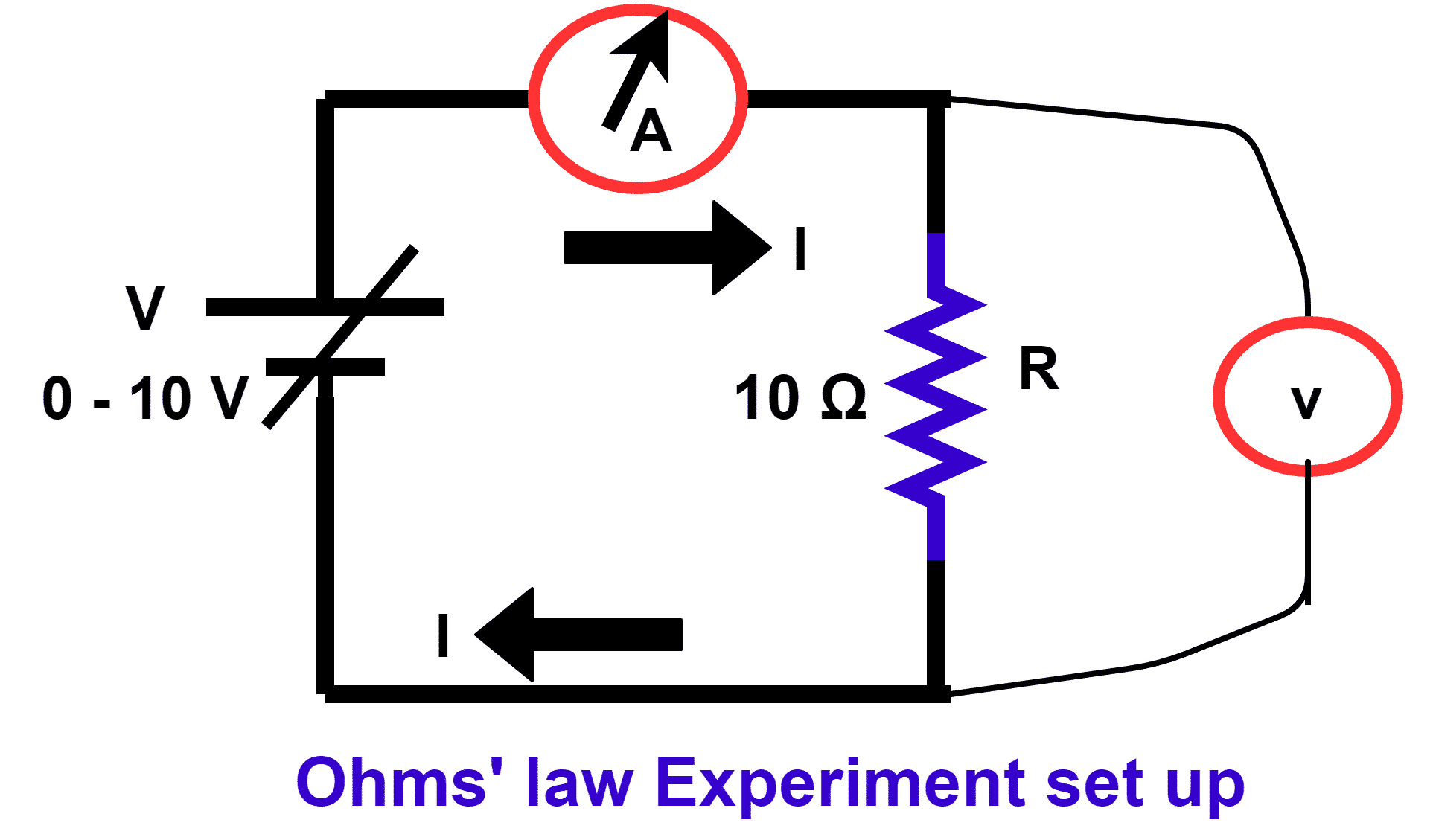
The current linearly increases with the increase in the potential drop across the resistance. The experiment setup of Ohm’s law is as given below. The variable voltage source is connected across the resistance.
Ohm’s Law Formula
We can write the equation V= IR in the following forms.
We can use the same formula by arranging it to calculate current and resistance respectively.
Derivation of Ohm’s Law
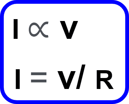
Starting from the basic proportionality:
I ∝ V
At a constant temperature, this proportionality can be expressed as an equation:
I=V/R
where R represents the resistance. Rearranging this equation gives the familiar form of Ohm’s Law:
V=I×R
Ohm’s Law Experiment Circuit: Relationship Between Voltage, Current and Resistance
Steps to Verify Ohm’s Law
- Set up the circuit
- Connect a resistor in series with an ammeter and a variable power supply.
- Attach a voltmeter across the resistor to measure the voltage drop.
- Turn on the power supply
- Begin with a low voltage to prevent any damage to the resistor.
- Record the readings
- Gradually increase the voltage in steps (e.g., 2V, 4V, 8V, 12V, 16V, 20V).
- For each voltage, note the corresponding current displayed by the ammeter.
- Create a data table
- Organize your measurements into columns for Voltage (V), Current (I), and Resistance (Ω).
- Keep the resistor value constant throughout the experiment.
- Plot the graph
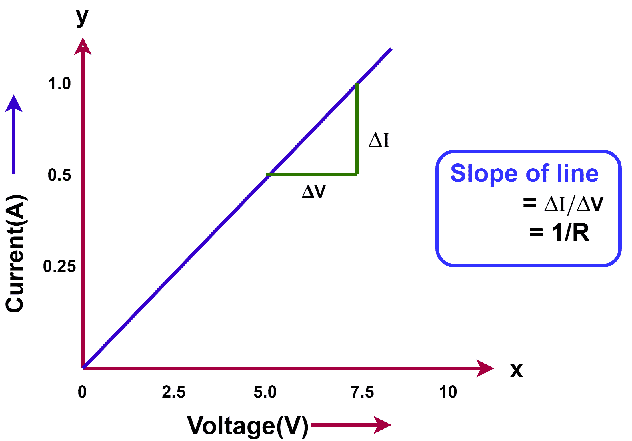
- Draw a graph with Voltage (V) on the X-axis and Current (I) on the Y-axis.
- For an ohmic resistor, the graph should be a straight line, confirming Ohm’s Law.
- Analyze the results
- Observe that the current increases proportionally with voltage.
- Verify that the slope of the line equals 1/R, representing the conductance of the resistor.
The results of the experiment are as per the table given below.
Ohm’s Law Worksheet
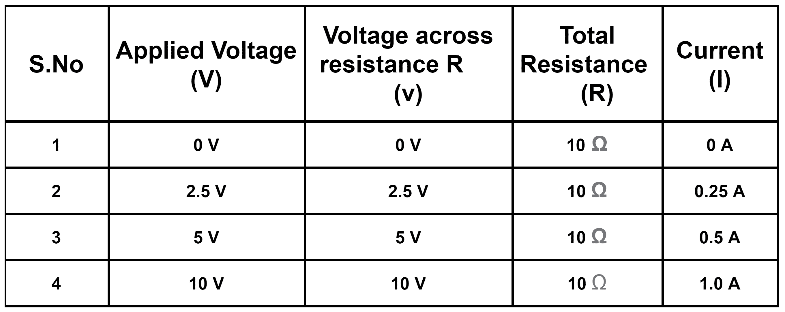
From above results, it is clear that the current flowing in the resistance is directly proportional to the voltage across the resistance. If we draw the graph between I and V, the graph is a straight line.
Graphical Representation of Ohm’s Law
The equation of the straight line is;
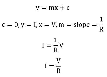
Mathematically, we can write this relationship as;
Where 1/R is the constant. R is the resistance of the circuit. We can write this equation in other forms as well.
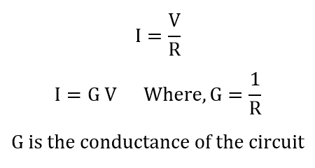
Ohm’s Law Expressed Using Conductance
Conductance, denoted as G, is the reciprocal of resistance, meaning G = 1/R. Using this relationship, Ohm’s Law can also be written in terms of conductance as:
I=G⋅V
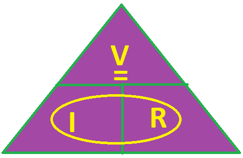
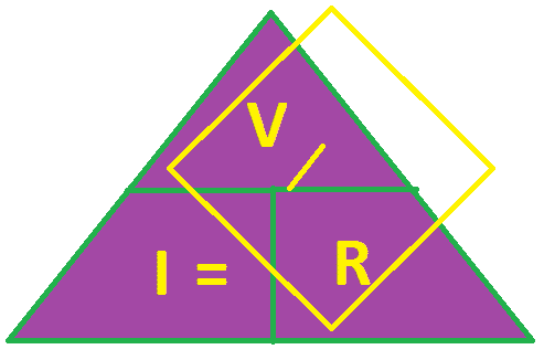
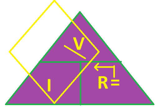
Ohm’s Law Magic Triangle
We can make use of the below-given magic triangle to remember the different equations of this law to solve for different variables(V, I & R).
Ohm’s Law Applications
The main applications of this law are as follows.
- To calculate the voltage, resistance, and current in the circuit.
- It is used to design the circuit to maintain the voltage drop across the circuit component.
- It is also for calculating the shunt resistance value for the DC ammeter to divert the desired current through the shunt. ( Shunt is a low-value resistance having negligible power loss)
- In resistance type ceiling fan regulator, resistance is selected using this law.
- We use this law for designing for current divider circuit.
- In a voltage divider circuit, we use this law to get desired output voltage across the voltage dividing resistor.
Limitations of Ohm’s Law
The followings are the limitations;
- The current can flow in one direction in unilateral devices like diode and transistor. This law is not applicable because these devices allow the current to flow through in one direction only. This law is not applicable to unilateral devices.
- The non-linear devices do not draw the current in the same proportion of the applied voltage. The reason for nonlinearity in voltage and current is the changing resistance of the non-linear devices. The resistance of non-linear devices does not remain constant. Therefore, this law is not applicable to non-linear devices. Examples of non-linear devices are SCR, thyristor, IGBT, etc.
Read detailed article: Limitations of Ohm’s Law
Ohm’s Law Solved Problems
Example 1: If the resistance of an electric kettle is 60 Ω and a current of 4 A flows through the resistance. Find the voltage between two points.
Solution:
Here, I = 4 A, R =60 Ω
voltage ( V) = IR
Substituting the values in the equation, we get
V = 4 X 60
V = 240 Volts
Example 2: Determine the amount of current going through a 100Ω; resistor with a voltage of 100 V.
Solution:
R = 100 Ω
V= 100 Volts
I = 100/100 = 1 Amps.
Example 3: Find the current I through a resistor of resistance R = 3 Ω if the voltage across the resistor is 6 V.
Solution:
R = 3 Ω
V= 6 Volts
I = V/R
I = 6/3 = 2 Amps.
Conclusion
Ohm’s Law forms the cornerstone of both electrical engineering and physics. By establishing a clear link between voltage, current, and resistance, it allows for straightforward analysis and design of electrical circuits. Regular practice with examples and applying this principle to real-world situations helps build a strong understanding of electricity and how circuits behave.
Related Articles :
- Temperature Coefficient of Resistance
- What is Electrical Resistance? Definition and Unit of Resistance
- Resistance and Resistivity
- What is Millman’s Theorem? Millman’s Theorem Formula
- Maximum Power Transfer Theorem
- A 20 ohm shunt is joined with an ammeter with 200 ohm resistance. It is joined to a 10v battery having a resistance of 4 ohm. What will the observation of the ammeter be?
- The resistance of L length wire is R. If half of its length stretch such as the total length becomes 2L what will be the final resistance?
- Coulomb’s Law – Statement, Formula, Limitations & Applications Explained
1 thought on “Ohm’s Law-Satatement, Formula, Solved Examples”