A cable megger test measures the insulation resistance of electrical cables using a megger to ensure safe and reliable cable performance.
This article describes the step-by-step procedure for testing cables with a megger. An electric cable has two main parts: conductors and the insulation material surrounding them. The conductor should have minimum resistance to allow maximum current flow, while the cable’s insulation resistance must be very high to prevent current leakage to the earth.
If the cable insulation fails, a heavy fault current flows from the conductor to the armor and then to the earth point. The armor is maintained at earth potential, and the reliability of the cable depends on the quality of its insulation.
For engineers and electricians, following the correct megger test procedure for cables and accurately interpreting cable megger test values is crucial to ensure long-term reliability and safety of high-voltage installations.
What is a Megger and Its Purpose in Cable Testing
The test equipment used to test the cable insulation is known as megger. The megger is derived from megaohm because it measures insulation resistance in megaohm or even higher.
A megger is widely used in high-voltage and low-voltage cable testing to detect insulation faults, deterioration, or leakage before they lead to equipment failure or safety hazards. By applying a high voltage to the cable and measuring the resistance, it helps ensure that cables are safe, reliable, and performing within specified standards. Regular use of a megger can also prevent costly downtime and extend the lifespan of electrical cables.
Pre-Activities Before Cable Megger Test
The following activities must be performed before conducting a megger test on a cable.
- Switch OFF the circuit breaker, remove its control plug & rack out the breaker from the panel. Take the electrical work permit and apply the LOTO system on the panel.
- Open the HT Terminal cover of the feeder/motor/transformer.
- Discharge any accumulated static or capacitive charges on the cable by connecting an earthing rod between the cable conductor and the earth. All three conductors must be discharged following the same procedure.
- Remove both sides of cable connections from sending and receiving end feeder.
- Now, the cable is ready for the megger test.
Step-by-Step Megger Test Procedure for Cables
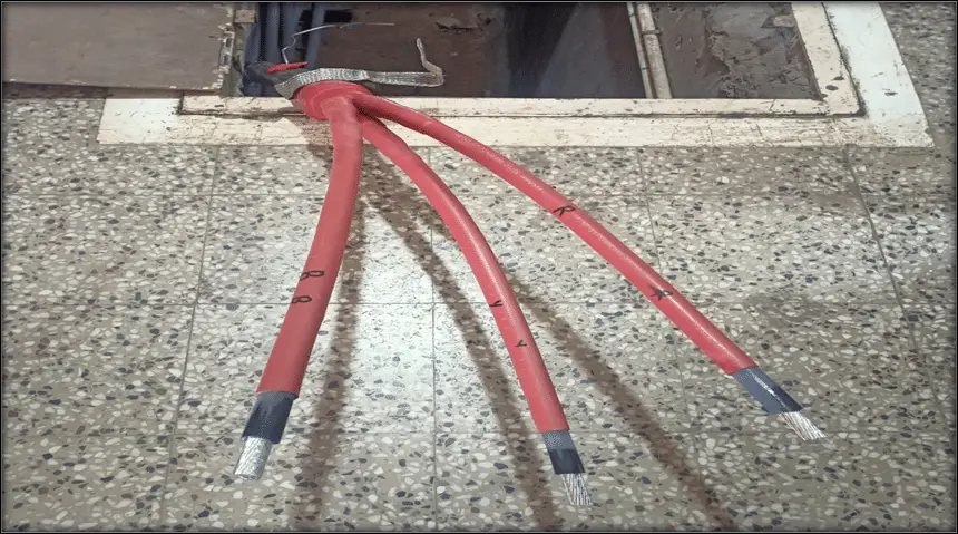
Step 1: Identify the cable and check its physical condition
Before starting the megger test of the cable you should first identify the cable and check its physical condition. The cable shown in the below picture is a 6.6 kV XLPE(E) cable
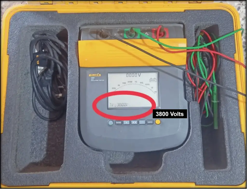
Step 2: Set the megger voltage to 3800 V(phase voltage)
Set the megger voltage for the phase voltage. In our case, we are testing a 6.6 kV cable, its phase voltage is √3 times of line voltage. Therefore its phase voltage is 1.732 X 6.6= 3.8kV=3600 Volts. Set the megger voltage to 3800 volts.
Do not connect the cable to the megger equipment before setting the megger voltage.
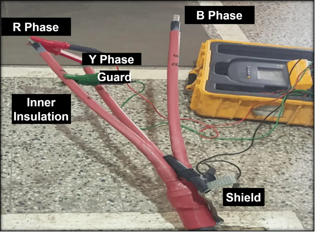
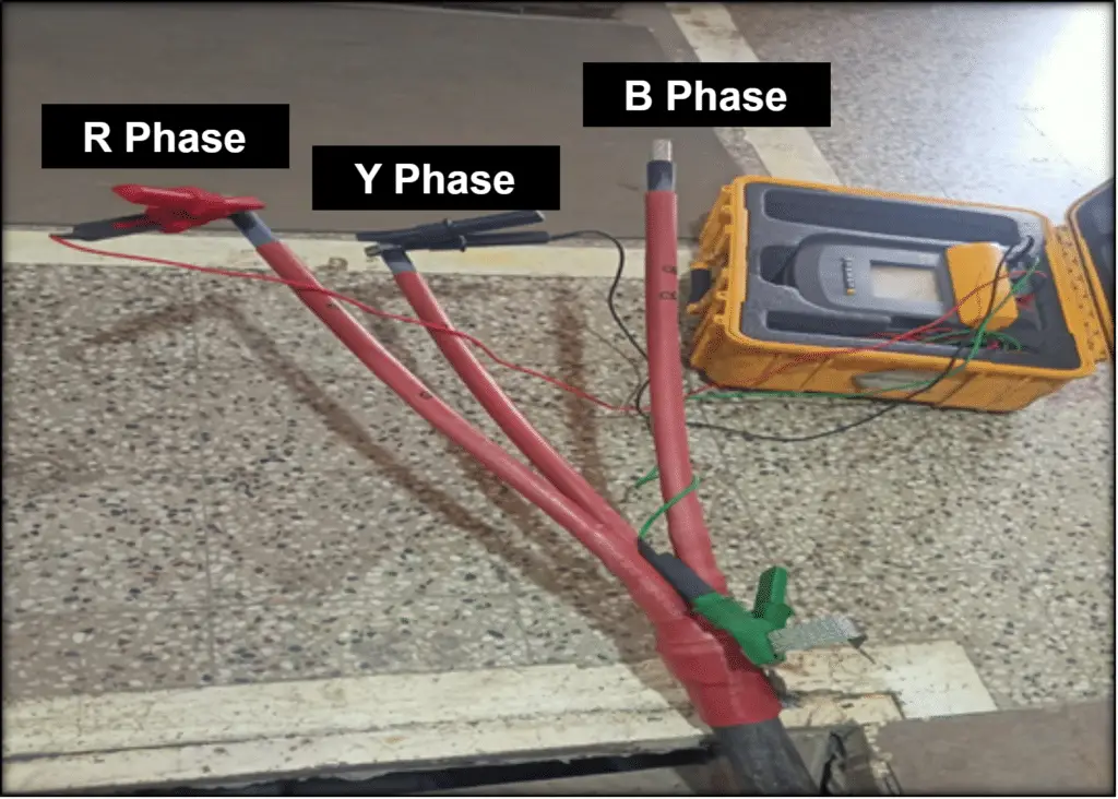
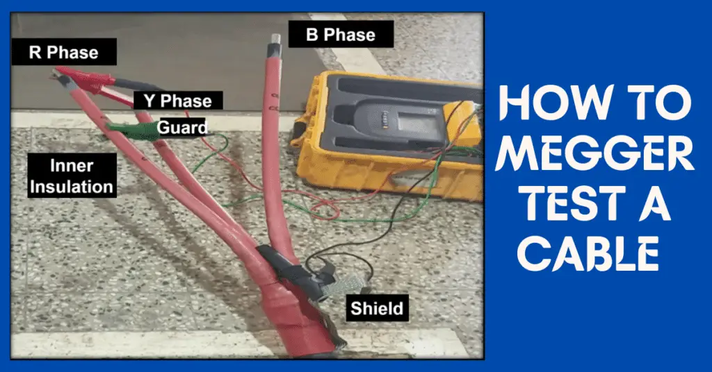
Step 3: Connect RED to R Phase, BLACK to shield, GREEN to guard terminal
Now, connect the RED lead of the megger to one of the conductors of the cable, we here designate it as R Phase, and BLACK lead to the shield point of the cable.
Connect the Green Lead of the megger to the inner insulation of the cable. The green lead is connected to the guard terminal of the megger. The guard terminal connection improves reading accuracy.
For high voltage cables, you will get more accurate results of the megger test on cable if you connect the guard terminal to the inner insulation of the cable through GREEN lead.
Step 4: Press the test button and wait 1 minute for the reading to stabilize
Press the test button on Megger, it will feed 3800 volts between the conductor and shield of the cable. Wait for about 1 minute to settle the value of insulation resistance. Initially, it will show less megger value because of the cable capacitance. finally, the value will be steady and this value is the insulation resistance of the cable core under test.
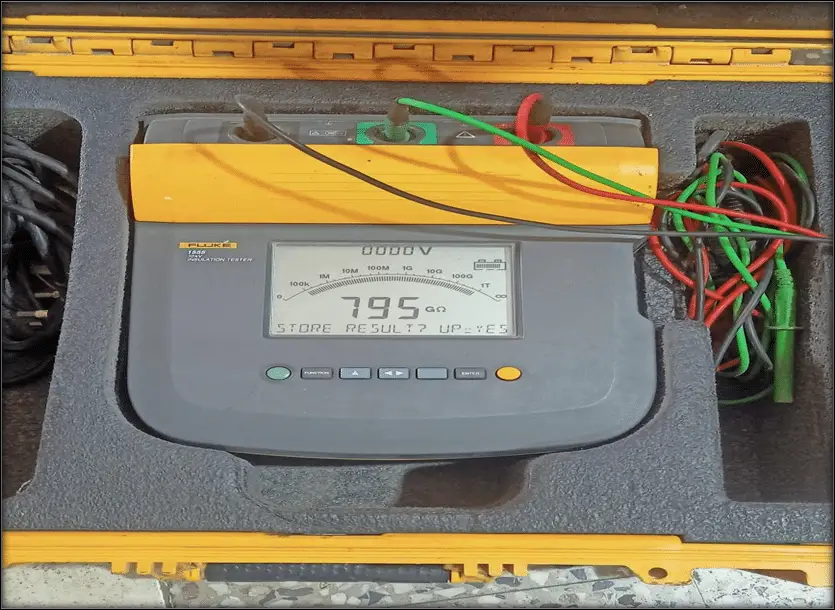
The megger or insulation resistance value of one phase conductor is 79.5 GΩ.
Step 5: Move the RED lead to Y Phase and repeat the test
Now, remove the red lead from the R Phase conductor and connect it to the second phase conductors ( Let it call Y Phase). Now repeat the same procedure as step-4 and note down the insulation resistance value. The Megger test value shows the insulation resistance of the R-phase conductor of the cable.
Step 6: Move the RED lead to B Phase and repeat the test
Now, remove the Red lead from the Y Phase conductor and connect it to the third phase conductor( Let it call B Phase). Now repeat the same procedure as step-4 and note down the insulation resistance value.
Step 7: Test phase-to-phase insulation with megger voltage set to 6600 V
Remove the Red and Black wire from the phase conductor and shield of the cable. In step-5,6 & 7 we tested the cable insulation for all phases.
Now, we will test the cable for its phase-to-phase insulation. First, set the megger voltage to 6600 volts.
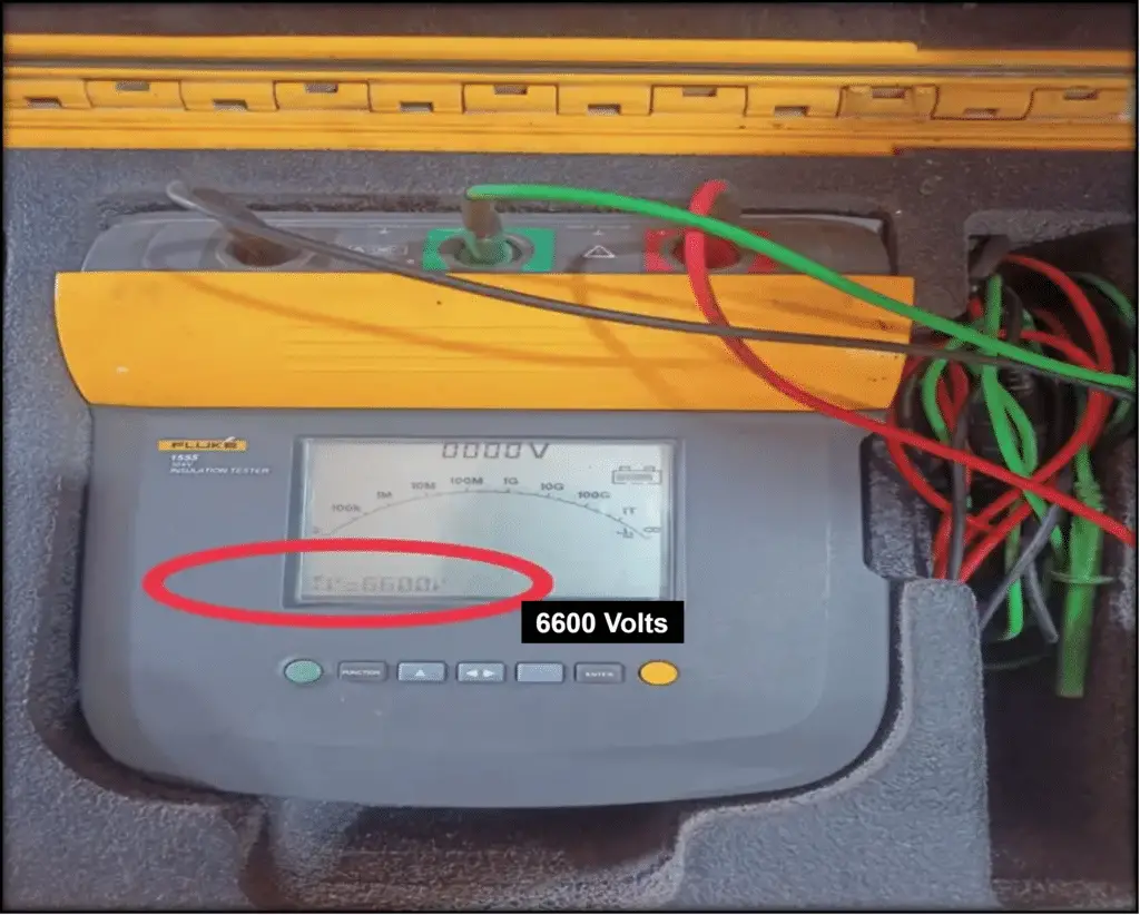
Step 8: Connect RED & BLACK to R and Y phases, press test button, wait 1 minute
Now connect the RED and BLACK leads of the megger to R and Y phases respectively. After that, start the test button. The megger will feed 6600 volts between the phases. Wait for about 1 minute to settle the value of insulation resistance.
Initially, it will show less megger value because of the cable capacitance. finally, the value will be steady and this value shows the phase-to-phase insulation resistance value of the R and Y phases of the cable.
Step 9: Connect BLACK lead to B Phase (RED on R Phase) and repeat the test
Now, Remove the black lead from the Y phase and connect it B phase and repeat the same procedure of step-8 and note down the insulation resistance value. The megger value shows the insulation resistance value between R and B phases.
Step 10: Connect RED lead to B Phase (BLACK on Y Phase) and repeat the test
Remove the red lead from the R phase and connect it B phase and repeat the same procedure of step-8 and note down the insulation resistance value. The megger value shows the insulation resistance value between Y and B phases.
Example Table for Phase Insulation Resistance
| Phase Test | Megger Voltage | Insulation Resistance |
| R Phase | 3800 V | 79.5 GΩ |
| Y Phase | 3800 V | 80 GΩ |
| B Phase | 3800 V | 78 GΩ |
| R-Y Phase | 6600 V | 65 GΩ |
| R-B Phase | 6600 V | 64.5 GΩ |
| Y-B Phase | 6600 V | 63.8 GΩ |
Safety Guidelines for Performing Megger Test
The following safety measures must be ensured for taking a megger test of cable.
- Personal safety equipment like dielectric hand gloves, dielectric gloves, and arc flash shield is mandatory.
- Prior to starting the megger test, carry out pre-job planning and risk assessment.
- Obtain safe work and isolation permit with LOTO before carrying out the job.
- Ensure personnel performing megger tests are authorized to do the job.
Conclusion
Performing a cable megger test is essential to ensure the insulation integrity and reliability of electrical cables. By following the step-by-step procedure, setting the correct megger voltage, and accurately reading insulation resistance values, engineers and electricians can detect insulation faults early, prevent equipment failure, and maintain safe operation of both HT and LT cables.
Regular megger testing not only extends the lifespan of cables but also helps in maintaining overall electrical system safety and compliance with industry standards. Always follow proper safety precautions and ensure that only authorized personnel perform the tests.
Related Articles:
- Why does Megger have DC Geneartor?
- Why is DC voltage applied in an insulation resistance test?
- What is a Megger? Principle, Advantages, Disadvantages
- Cables-Types, Uses, Benefits, and Challenges
- Current Carrying Capacity of Aluminium Cable
- Difference between Intrinsic Safe and Non-intrinsic Safe Cables
- Types of Underground Cables
- Difference between Power Cable and Control Cable
- Common materials used in instrumentation cable
- Difference between Flame Resistant and Flame Retardant Cables
- Cable Shielding – Purpose, Selection, Grounding
- Difference Between Copper & Aluminum Cables
- What is a Cable Gland?
- Selection Guidelines for Cable Glands
- Cable Power Loss Calculator, Formula, Calculation
- Electrical Cables Interview Questions & Answers
- Effects of Harmonics on Power Cables
- What is an Armoured Cable? Classification of Cables