This article describes the Hall effect sensor working principle and applications. Hall Effect is named after Edwin H Hall who discovered the basic fundamental principle of electromagnetism in the year 1879. The Hall Effect allows us to find out whether the charge carriers in a conductor are positively or negatively charged.
Theory of Hall Effect Sensor
The magnetic force on the moving charge can be represented as F= qV x B. At an equilibrium point, the net forces on the charges become zero.
Therefore,
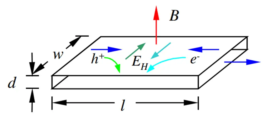
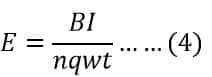
Figure 1: A conducting strip of length l, width w, and diameter d immersed in a magnetic field B
Let us consider a conductor of the following dimension: length L, thickness t, and width w as illustrated in Figure 1. The charge carrier of charge is q, charge carrier number density n, and charge carrier drift velocity vx. In Figure 1, E and B are mutually perpendicular vectors.
so,
The current across the conductor can be expressed as
Simplifying Eq(2) and Eq(3), we get
The transverse potential difference in the conductor can be represented as
Eq(5) can be rewritten as
Eq(6) clearly indicates the relationship of Hall voltage with carrier mobility, conductivity, and carrier concentration. Therefore, the selection of semiconductor material plays an important role in the design of Hall Effect sensors. Different alloy materials such as InSb, InAs, GaAs, and doped Si are used to construct Hall Effect sensors.
The overall sensitivity of the Hall Effect sensor is defined as Hall Coefficient which can be defined as the electric potential gradient per unit magnetic field intensity per unit current density.
Working Principle of Hall Effect Sensor
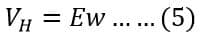
The Hall effect sensor working principle is based on the Hall voltage. Electrons flow in a straight line on a thin strip of a conductor upon application of electricity. However, when the charge particles come under the influence of the magnetic field, they get diverted in a perpendicular direction to the motion of electrons.
Some electrons get collected on one side while some are on another side. As a result, one of the conductor’s planes behaves becomes negatively charged and another plane becomes positively charged. The potential difference between the conductor’s plane produces voltage and this voltage is called the Hall voltage.
The electrons keep moving from one side of the plane to the other till an equilibrium is achieved between the force applied to charged particles. The equilibrium of forces is established when the force on a charged particle caused by an electric field and the force caused by a magnetic field become equal. Under this condition, the hall voltage value at this instant is the measure of magnetic flux density
The hall effect sensors can be categorized into two types-linear and threshold sensors, on the basis of the relation between hall voltage and magnetic flux density. The output voltage linearly increases with magnetic flux density in the linear hall effect sensor. On the other hand. in the threshold sensor, the output voltage sharply decreases at each magnetic flux density,
Design of Measurement System using Hall Effect Sensor
Using the fundamental principle of the Hall Effect, different sensors have been developed in various fields of applications. A Hall Effect effect measurement system comprises different components such as
- Hall Effect Sensor
- Signal Conditioning Element
- Signal Processing Element
- Display unit
- Regulated power Supply unit.
Hall Effect sensor is packed in four terminal housing that comprises of control terminal and the differential output terminal.
Signal Conditioning System for Hall Effect Sensor
A Hall Effect Sensor primarily senses the presence of a magnetic field and provides adequate voltage output depending on the presence of the magnetic field. In the presence of 1 Gauss magnetic field, the Hall Effect sensor provides 30 µV of analog output voltage.
The small amount of voltage output requires proper signal conditioning. Further, the Hall Effect is dependent on ambient temperature, therefore, temperature compensation is also required. Hall effect sensor is also susceptible to mechanical stress, therefore, proper housing of Hall Effect is designed to minimize the stress.
Figure 2 shows the schematic diagram of the analog signal conditioning circuit of the Hall Effect sensor.
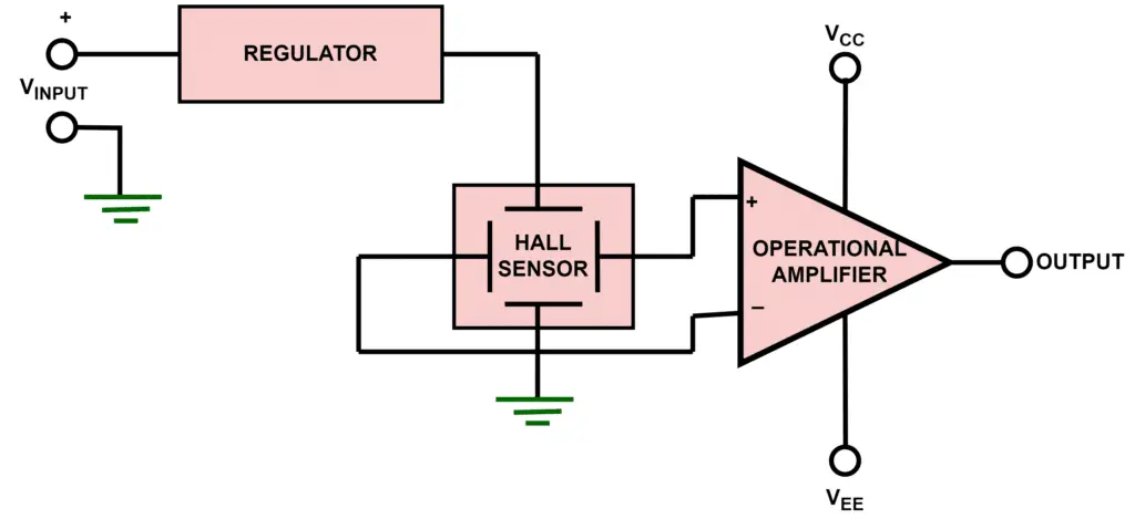
Figure 2: Analog signal conditioning
For signal conditioning purposes, a differential amplifier is used that has the following characteristics
- High input impedance
- Low noise level
- High amplification gain
Some of the important design steps of the signal conditioning unit of this sensor have been discussed below.
- As the measured magnetic field, has positive as well as negative polarity, the signal conditioning circuit of the Hall Effect also provides positive as well as negative voltage. To avoid using two different polarity power supplies to accommodate the positive as well as negative polarity voltage, an offset circuit is used.
- For saturation of positive and negative voltage of the Hall Effect, saturation limits are imposed.
- The Hall Effect output voltage depends on current, therefore, a regulator is used to regulate the flow of current
Figure 3 illustrates the signal conditioning system for the Hall Effect sensor with digital output. The important benefit of the digital sensor is that it will provide either logic 1 or logic 0 when there is the presence or absence of the magnetic field. It is easier to connect the digital output of the sensor with a microprocessor, microcontroller, and other digital devices.
To get the digital output, the analog output of the difference amplifier is passed through a Schmitt trigger circuit. The Schmitt trigger circuit provides a comparison between the actual value and the pre-set value and provides either logic 0 or logic 1. The output driving capability of the digital output of the sensor is very low, therefore, open collector configuration (NPN transistor) and open drain configuration have been used at the output stage.
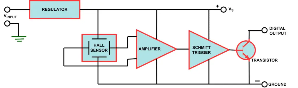
Figure 3: Digital signal conditioning of Hall Effect Sensor
Applications of Hall Effect Sensor
Hall Effect Current Sensor
The Hall Effect has applications in different sensor design disciplines. One such promising sensor design is the Hall Effect Current Sensor (HECS). HECS measure AC as well as DC current because classical current transformer can’t measure DC. HECS finds a large number of applications in different domains such as industrial DC and AC drives, electrical vehicles, power and energy measurement, power quality measurement, and feedback control mechanisms for power converters.
Selection of appropriate HECS is an important design challenge due to various factors such as
- Current range: Peak current, transient overload current, nominal current
- Required output: Voltage, the scaling factor
- Accuracy: Considering the nonlinearity and DC offset at ambient temperature
- Power Supply: Positive or negative power supply
- Frequency Range: Fundamental operating frequency, Harmonic content
- di/dt and dv/dt rating: Rate of change of current and voltage limit
There are different challenges to designing HECS such as
- HECS should have a high dynamic range
- HECS should have a low physical footprint or dimension
- HECS should be of high speed
- HECS should be economical in nature
There are different kinds of HECS i.e. open-loop HECS and closed-loop HECS. Open-loop HECS have different limitations such as larger physical size, saturation, nonlinearity, and heating of the core, therefore, closed-loop HECS are widely used as shown in Figure 4.
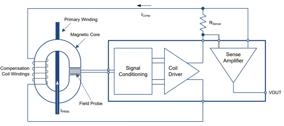
Figure 4: Block diagram of closed-loop Hall Effect Sensor with signal conditioning circuit
Despite its several features, closed-loop HECS has several limitations such as (a) gain drift due to change in temperature, (b) magnetic offset, (c) DC offset, and (d) Nonlinearity
Table 1: Summary of different Hall Effect current sensors
| Part Number | Bandwidth (MHz) | Slope Rise time (nsec) | DC Signal measurement | Isolation | Size | Rating |
| ABB EL50P1 | 0.2 | — | Yes | Yes | Medium | RMS: 50 A P-P: ±80 A |
| LEM LA-55-P | 0.2 | 500 | Yes | Yes | Medium | RMS: 50 A P-P: ±70 A |
| ACS70331 | 1 | — | Yes | Yes | Small | 5 A |
| ACS7002MA | 0.4 | — | Yes | Yes | Small | ±100 A |
Hall Effect Switch
Hall Effect sensors are also used as switches such as proximity switches, and reed switches. The Hall Effect switch turns ON and OFF if it detects the presence of a magnetic field. This switch is widely used for proximity detection principles. Some of the industrial Hall Effect switches are
- TLE496X: Automotive field
- TLI496X: Industrial purposes (position detection of BLDC motor)
- TLV496X: Consumer applications (E-bikes, Fans)
For sensing the velocity, displacement, and position of a rotating shaft, Hall Effect sensors are widely used. There are two different motor assembly configurations where the Hall Effect sensors are used for position and displacement sensing such as
- Magnetic rotor assembly: In this assembly the magnets are non-stationary
- Ferrous vane rotor assembly: In this assembly the magnets are stationary