An ideal transformer is an imaginary or hypothetical model of a transformer that has zero energy losses in it. whereas a practical transformer has energy loss in it and has an efficiency lower than 100%.
A transformer transfers the power from the primary side to the secondary side by stepping up or down the voltage. The power at the primary and secondary sides of the transformer remains almost constant, ignoring the losses in the transformer. The transformer does not alter the frequency.
What is an Ideal Transformer?
When we input power into a machine and get the exact power in its output, then we can say the machine is 100 % efficient. In an ideal transformer, we assume that the input power is equal to the output power after the transfer of energy. However, it is next to impossible to have this condition in the transformer, even not in any electrical or mechanical machines. In a real scenario, the losses in the form of heat loss always take place in the machine. And, therefore, 100 % efficiency is the myth. practice. Therefore, we can say that an ideal transformer is hypothetical and can not be realized practically.
A transformer converts electrical energy into magnetic energy and the magnetic energy is again converted into electrical energy according to Faraday’s law of electromagnetic induction. The magnetic energy in the transformer is the flux that flows in the magnetic core of the transformer.
An ideal condition of conversion of electrical energy into magnetic energy in the primary and conversion of magnetic energy into electrical energy in the secondary of the transformer depends on the amount of flux linking in both windings. For an ideal transformer, all the flux produced in the primary must link to primary and secondary winding without leaking out of the magnetic core.
Thus, the entire flux generated by the primary winding must be linked to the primary as well as to the secondary winding. We can achieve this condition only if there is no flux leakage in the core. This is an ideal condition. But, it is impossible to achieve this condition. In a transformer, some amount of flux leaks through the transformer core. and cause hysteresis loss. The leakage flux also introduces leakage reactance in a practical transformer. In an ideal transformer, we consider leakage reactance zero.
The primary and secondary winding of a transformer is made of copper or aluminum. The copper and aluminum conductor has finite resistance and causes copper loss (I2R) when secondary winding is connected to the load. We can get zero copper loss only when both windings have zero resistance of both the winding is zero. However, it is impossible to have zero resistance of copper or aluminum conductor. This is a purely imaginary condition. Therefore, an ideal transformer has zero copper loss.
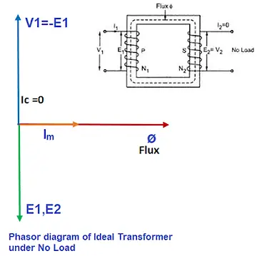
The core loss component of the current is zero in an ideal transformer, therefore magnetic flux and the exciting or magnetizing current are in phase. This condition can be achieved only if the B-H or magnetization curve is linear.
What is a Practical Transformer?
A practical transformer has a core loss component, and therefore the exciting current and magnetic flux are not in phase. The magnetizing current leads the magnetic flux by angle “α” called the hysteric angle. A practical transformer has a nonlinear B-H curve and becomes flat with the increased magnetizing current.
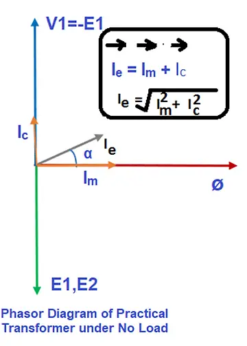
From the above phasor diagram, it is clear that the practical transformer has-
- Core loss
- Copper loss
- Exciting current not in phase with magnetic flux.
A summary of the main difference between an ideal and practical transformer
- An ideal transformer has zero copper and iron loss, on the other hand, a practical transformer has finite core and copper loss.
- An ideal transformer is 100 % efficient. The efficiency of an ideal transformer is 100%. A practical transformer has less than 100 % efficiency. The efficiency of the practical transformer depends on the loading and power factor.
- There is no ohmic resistance drop (IR) in an ideal transformer. Therefore, its voltage regulation is 0 %. A practical transformer has voltage regulation of more than 0%.
- In an ideal transformer, The flux generated in the primary gets fully linked to both primary and secondary winding and there is zero flux leakage. The leakage flux always exists in a practical transformer.
- An ideal transformer is hypothetical and imaginary and can not be practically realized.
Key differences between Ideal Transformer and Practical Transformer
The key differences between an ideal transformer and a practical transformer are as follows.
| Basis of Difference | Ideal Transformer | Practical Transformer |
|---|---|---|
| Definition | An ideal transformer is a hypothetical model and it does not have energy loss in it. | A practical transformer is a real transformer and it has energy loss in it. |
| Core losses | It has zero no-load losses( Hysteresis & Eddy current losses) | It has zero finite no-load losses( Hysteresis & Eddy current losses) |
| Copper losses | Zero | Finite copper loss |
| Efficiency | 100 % | < 100 % |
| Dependency of efficiency | The efficiency does not depend on any parameter. It is always 100%. | The efficiency of a practical transformer depends on; 1. power factor 2. Loading on the transformer. |
| Winding resistance | Zero | Finite Value |
| IR drop | Zero because resistance is zero. | finite ohmic drop due to the resistance of the winding. |
| Nature of winding coils | Purely inductive | The winding has some resistance. |
| Magnetic flux leakage | zero | The practical transformer has a finite leakage flux. |
| Permeability of core | Infinite | It has finite permeability. |
| Existence | Imaginary | Real |
| Applications | For Analysis Purpose | Used as a step-up and step-down transformer. |