This article describes the anti-pumping relay, its definition, function, and circuit diagram. In a circuit breaker it is desired that when close and trip operation is performed on the circuit breaker with the closing coil energized, the subsequent closing operation should be prevented. So let’s begin with the basic introduction of the anti-pumping relay.
What is an Anti-Pumping Relay?
The anti-pumping relay is a circuit breaker auxiliary relay that is used to protect the circuit breaker from multiple closing commands. In other words, the anti-pumping relay is one that is used in the circuit breakers to prevent unwanted closing of the circuit breaker after tripping.
The anti-pumping relay is important when the TNC (Trip-Normal Close) switch in the circuit breaker closing circuit releases continuous circuit breaker close commands to the closing coil. The anti-pumping relay prevents this unwanted closing of the circuit breaker that may cause a safety hazard or equipment failure.
The anti-pumping relay is basically a NO contact. This means, when the circuit breaker is in the closed condition, the relay will be in NO condition, and when the circuit breaker is in the open state, the relay will be in NC condition.

Different circuit breaker manufacturers use different APDs of their own choice, it can be a relay or a high-speed contactor. Both options serve the purpose of an anti-pumping feature.
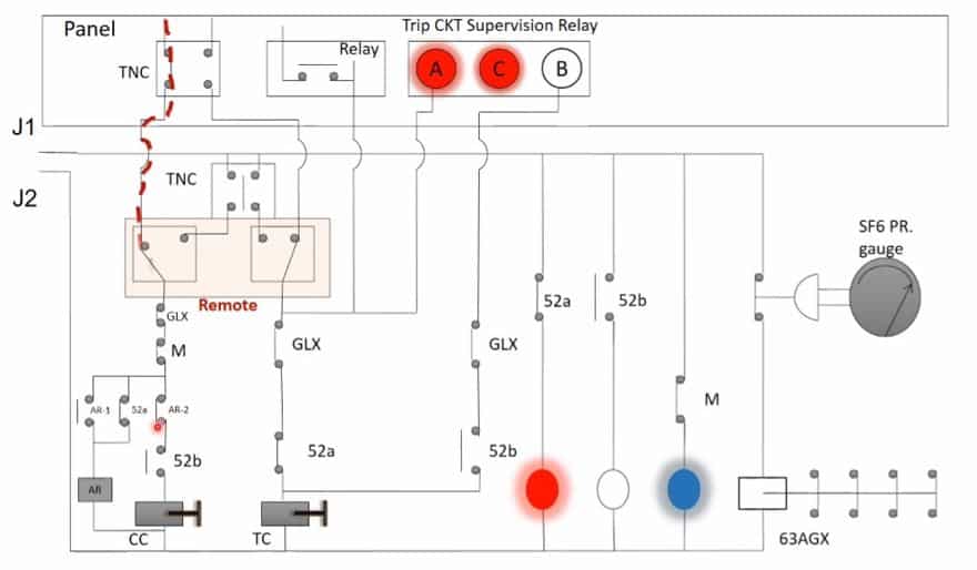
Circuit breaker closing and tripping Diagram without Anti-pumping Features
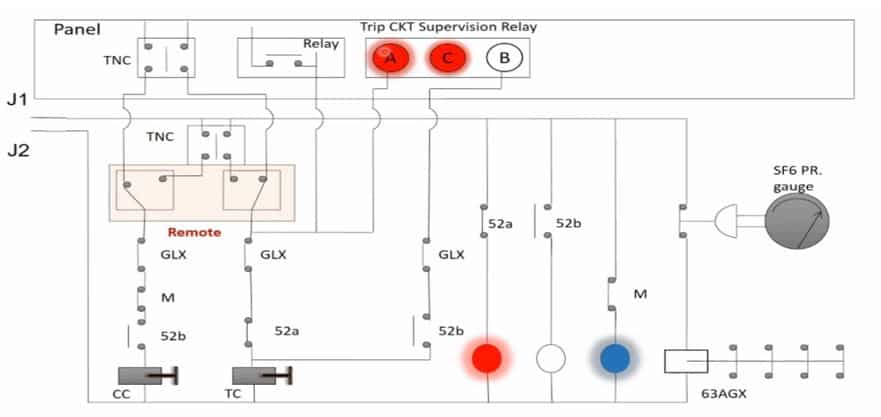
Closing function: Above diagram shows the breaker in closed condition. When the TNC switch is operated towards close and aux contact 52b remains in the NC position, the breaker gets closed and a contact changeover takes place thus opening the 52b contact and closing the 52a contact of the trip circuit.
Tripping function: Above Diagram shows trip operation, when any fault occurs in the relay contacts change to NC position thus energizing the trip coil as aux. contact 52a was in close condition prior to tripping.
Anti-Pumping Relay Circuit Diagram
The circuit diagram of the anti-pumping relay is shown in the following figure.
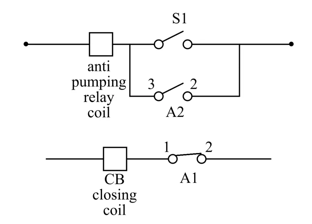
A DC contactor is used as the anti-pumping relay in the circuit breaker. The normally closed (NC) contact of the relay is connected in series with the closing coil of the circuit breaker. Therefore, when the anti-pumping relay is not operating, the dc closing command of the circuit breaker is extended to the circuit breaker closing coil. On the other hand, if the anti-pumping relay is operated, the NC contact will become NO and it stops the dc command of the circuit breaker closing circuit.
Anti-Pumping Relay Working
As shown in the above circuit, the anti-pumping relay is connected in series with the circuit breaker closing circuit. The anti-pumping relay uses the dc closing command for its operation. From the circuit diagram, S1 and A2 both are the NO (Normally Open) contact of the relay and change their position based on the operation of the relay.
In actual practice, the circuit breaker closing command is provided for 100 ms for the operation of the circuit breaker closing coil. After closing the circuit breaker, the S1 contact is changed from NO to NC.
If the dc closing command is continuously available and the circuit breaker is in the closed position, the dc closing command will extend to the relay and the relay will operate. After operating the anti-pumping relay, the A2 constant of the relay will be changed from NO to NC, and the dc closing command will now extend through the A2 contact.
Now, if the circuit breaker is tripped, the switch S1 will be changed from NC to NO. Although, the anti-pumping is still in operation through switch A2, and will prevent further closing of the circuit breaker.
How does Anti-Pumping Relay prevent repetitive closing commands?
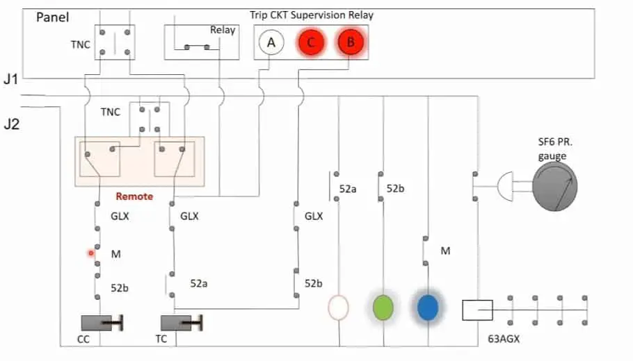
The control circuit diagram of the circuit breaker without an anti-pumping relay is given below,
If the TNC switch remains in a close position due to any issue within it or the operator keeps it in a close position, during fault conditions, both close trip commands will remain in the circuit causing repeatedly closing and tripping the breaker. This type of operation will cause damage to the circuit breaker and power system because of the high magnitude of the fault current.
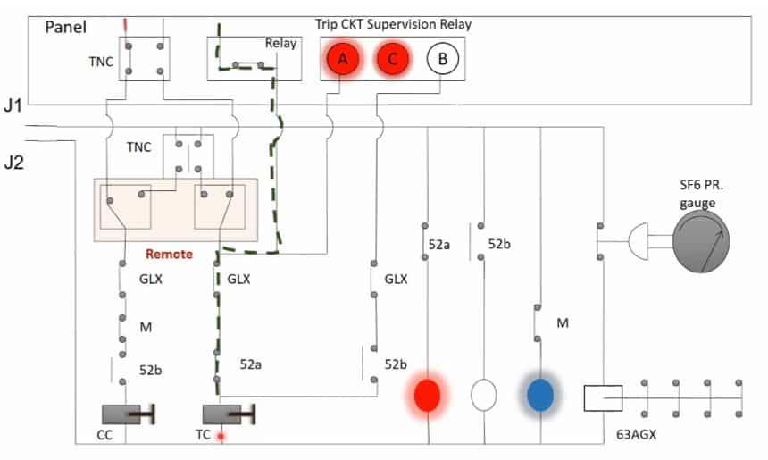
To avoid such a problem, an anti-pumping relay is incorporated into the closing circuit as shown in the figure below
Note – Anti-pumping relay is mandatorily used in all types of circuit breakers to prevent unwanted closing of the circuit breakers.