Magnetomotive force (MMF) is a key concept in magnetic circuits, comparable to how voltage works in electrical circuits. It plays a vital role in creating and maintaining magnetic flux in devices like transformers, inductors, and motors.
For students and professionals in electrical engineering, it is important to know the MMF full form, MMF definition, MMF SI unit, and its applications in electromagnetic systems.
What is Magnetomotive Force (MMF)?
Definition: Magnetomotive force (MMF) is the magnetic pressure that sets up the magnetic flux in the magnetic circuit. Without MMF, it is not possible to set up flux in the magnetic circuit. In this context, MMF in a magnetic circuit is analogous to the electromotive force in an electric circuit.
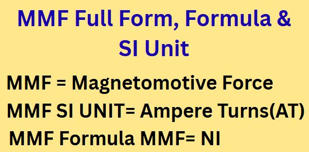
The MMF full form is Magnetomotive Force. It is one of the fundamental terms used in magnetic circuits, much like voltage (EMF) in electrical circuits.
The electromotive force accelerates the electrons and thus the current flows in the electric circuit. Similarly, the MMF set up flux in the magnetic circuit. The magnitude of the flux in a magnetic circuit depends on the magnetomotive force and the reluctance of the magnetic circuit. Furthermore, MMF of the magnetic circuit depends on the number of turns in a coil and the magnitude of the current. We denote the MMF by the letter F.
In simple terms, MMF in electrical engineering refers to the force that drives magnetic flux through a magnetic path, just as voltage drives electric current through a conductor.
Magnetomotive Force (MMF) Formula
The MMF formula is as follows:
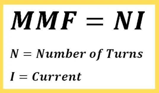
F = NI
Where N is the number of turns and I is the current
This MMF formula in electrical engineering shows that magnetomotive force is directly proportional to both coil turns and current and it is used to calculate magnetomotive force in electrical systems.
Magnetomotive Force(MMF) Unit
The SI unit of MMF is Ampere-Turn (AT).
- Ampere (A): Current flowing through the coil
- Turn (T): Number of turns of the winding
The MMF unit in the SI system is Ampere-Turns (AT), which means the product of current in amperes and the number of coil turns. Thus, 1 Ampere-Turn means a current of one ampere flowing through a coil of one turn.
This unit is used in transformer design, magnetic circuit analysis, and other electrical applications.
In the CGS system, the unit of MMF is Gilbert (G).
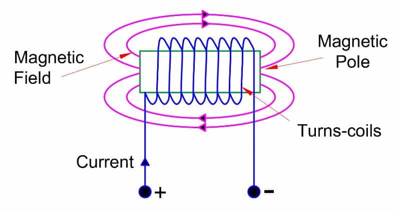
To illustrate furthe, let us understand the meaning of MMF by taking an example of a coil wound on magnetic material.
Magnetomotive Force of Inductive Coil
The MMF of the inductive coil in the figure is calculated as:
The MMF of the inductive coil is calculated as:
F = NI
Where:
- N – number of turns of the inductive coil
- I – current flowing through it
Clearly, the strength of the MMF is equal to the product of the current flowing in a coil and the number of turns. The work is done to move the unit magnetic pole(1 Weber) in a magnetic circuit.
In fact, in electrical systems, magnetomotive force is crucial in determining how much magnetic field is generated within inductors, solenoids, and cores.
MMF Formula in Terms of Magnetic Relucatnce and Flux
MMF is the magnetic potential that sets up the flux in the magnetic circuit.
The Magnetomotive Force (MMF) is related to magnetic flux (Φ) and magnetic reluctance (R) and can be calculated using the formula:
Flux = MMF/ Reluctance
Therfore,
MMF = Flux X Reluctance
F= Φ X Rm
The opposition offered by a magnetic material is magnetic reluctance.
This equation explains how MMF relates to magnetic reluctance and flux — core concepts in magnetic field theory and electromagnetic design.
Solved Problems on MMF
Example 1: A coil of 100 turns is wound uniformly over a wooden ring that carries a 2-ampere current. Calculate MMF.
F = NI
= 100 x 2
= 200 AT
Example 2: Calculate the magnetomotive force required to produce a flux of 0.020 Wb (Weber)across an air gap 2.0 mm long, having an effective area of 200 cm2
ϕ = 0.020 Wb, l = 2.0 mm = 2.0×10⁻³ m, A = 200 cm2 = 2×10⁻² m2
B = ϕ / A
= 0.020 / (2×10⁻²)
= 1 T
H = B / μ0
=1 / (4π×10-7)
= 7.96×10⁵ A/m
F (MMF) = H.l = 7.97×105 × 2.0 ×10-3 = 1.59×10³ AT
Conclusion
MMF in electrical systems stands for Magnetomotive Force, a fundamental concept in magnetic circuit analysis. It is defined as the force that drives magnetic flux through a core, in the same way that voltage drives current.
The MMF full form in electrical is Magnetomotive Force. The MMF definition and the SI unit of MMF (Ampere-Turn) are essential in understanding electromagnetism. The standard MMF formula, F = NI, shows its dependence on current and coil turns.
Whether you’re looking to define MMF, understand its role, or apply it in transformer and inductor design, this concept is central to magnetic systems in electrical engineering.
FAQs on MMF( Magnetomotive Force)
MMF full form in electrical is Magnetomotive Force.
The SI unit of MMF is Ampere-Turn (AT).
The MMF formula is F = NI, where N is the number of turns and I is the current.
Magnetomotive Force (MMF) in electrical circuits is calculated using the formula:
MMF=N×I
Example: If a coil has 200 turns and carries a current of 3 A, then:
MMF=200×3=600 AT
Related Articles: